


DP200 Page 31
Specifications
Inputs
Two electronically balanced.
Impedance
> 10k ohms.
CMRR
>65dB 50Hz - 10kHz.
Outputs
Four electronically balanced.
Source Imp
< 60ohms.
Min. Load
600ohm.
Max. Level
+20dBm into 600 ohm load.
Frequency Resp
.
±
0.5dB 20Hz - 20kHz.
Dynamic Range
>103dB 20Hz -20kHz. unwtd.
Distortion
< 0.02% @ 1kHz, +18dBm.
Maximum Delay
682 mS. (increment 21
µ
S)
Output gain
Adju15dB to -40dB in 0.1dB steps and mute.
Input gain
Adjustable 0dB to -40dB in 0.1dB steps. (crossover
modes only)
Parametric Equalisation
Filters
8 Sections per output ( 16 in Dual mode).
Filter gain
+15dB to -30dB in 0.1dB steps.
Centre frequency
20Hz - 20kHz, 1/24 octave steps. (240 positions)
Filter Q
0.4 to 128
(Sections 1 & 2 switchable to Shelving response)
Low frequency
20Hz - 1kHz
High frequency
1kHz - 20kHz
Shelf gains
±
15dB in 0.1dB steps.
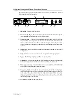
High and Lowpass Filters
Filters
1 of each per output.
Frequency (HPF)
10Hz - 16kHz, 1/24 octave steps.
Frequency (LPF)
60Hz - 22kHz, 1/24 octave steps.
Response
Bessel / Butterworth 12/18/24dB per octave and
Linkwitz-Riley 24dB per octave.
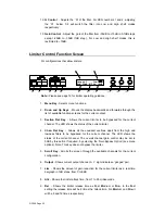
Limiters
Threshold
+20dBu to -27dBu (dependant on operating level).
Attack time
1 to 99 milliseconds.
Release time
4, 8 or 16 times the attack time.(
S
low,
M
edium,
F
ast)
Operating level
Headroom sele3dB, +8dB, +15dB & +20dB.
Display
2 x 20 character backlit LCD.
Headroom meter
2 x 7 point, -30dB to clip.
Connectors
Inputs
3 pin female XLR.
Outputs
3 pin male XLR.
MIDI
In / Out / Thru 5 pin DIN.
Power
3 pin IEC.
Power
110 / 220 V
±
15% @ 50/60Hz.
Consumption
< 20 watts.
Weight
3.5kg. Net (4.8kg. Shipping)
Size
1.75"(1U) * 19" * 11.8" (44 * 482 * 300mm) excluding
connectors.
Optional Interfaces
RS232 (9 way DEE), RS422 (9 way DEE) and RS485
(8way RJ45 x 2). These options also provide closed-
contact memory recall via 8 pin DIN socket.
Options
= Transformers available.
Relay bypass. Digital I/O.
Due to continuing product improvement the above specifications are subject to change
.


