


DP200 Page 9
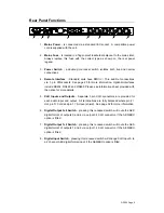
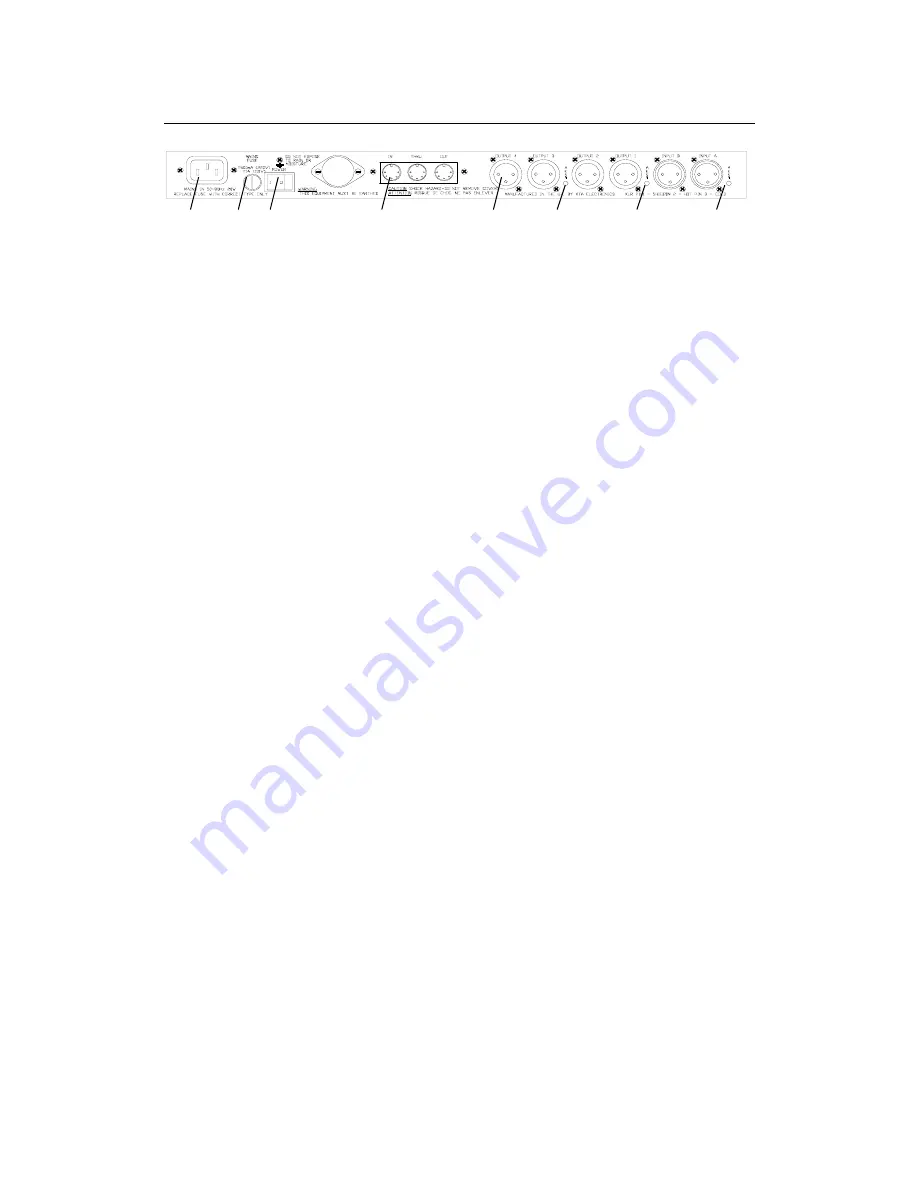
Rear Panel Functions
1.
Mains Power
- is connected via a standard IEC socket. A compatible power
cord is supplied with the unit.
2.
Mains Fuse
- is located in a finger-proof fuseholder adjacent to the mains inlet.
Always replace this fuse with the correct type as shown on the rear panel
legend.
3.
Power Switch
- a double pole rocker switch isolates both live and neutral
connections.
4.
Remote Interface
- Standard units have MIDI In / Thru and Out connections
via 5 pin DIN sockets. See page 25 for more information. Optional interfaces
include RS232, RS422 and RS485. Please see information sheet provided with
the option for more details.
5.
XLR Inputs and Outputs
- Separate 3 pin XLR connectors are provided for
each audio input and output. All terminations are fully balanced where pin 2 =
Hot, pin 3= Cold and pin 1 = Screen (shield). See page 32 for more information.
6.
Digital Output 3+4 Switch
- pressing this recessed switch will route the AES
digital format of outputs 3 and 4 via output 3's XLR connector, if the AES/EBU
option is fitted.
7.
Digital Output 1+2 Switch
- pressing this recessed switch will route the AES
digital format of outputs 1 and 2 via output 1's XLR connector, if the AES/EBU
option is fitted.
8.
Digital Input Switch
- pressing this recessed switch will change XLR Input A to
a 2 channel AES digital format input, if the AES/EBU option is fitted.
1
2
3
4
5
6
7
8


