X
X
X
T
T
T
E
E
E
E
E
E
L
L
L
E
E
E
C
C
C
T
T
T
R
R
R
O
O
O
N
N
N
I
I
I
C
C
C
▫
User’s Manual
▫
9
▪
11
11. Protection Systems
In addition to the usual protection consisting of
fuses, these products are complete of different
protection devices in order to safeguard them
from possible risks of damage.
11.1. Power Output Short Circuit
Applying a lower loading impedance than the
rated value means requiring the equipment to
supply a power higher than it can do on a
continuous basis.
In order to avoid this problem, the units are
equipped with a circuit protecting them against
overloads that protects automatically.
The protection circuit will be tripped immediately
on the amplifier if any of the following cases
occurs:
Short circuit on one of the loudspeaker
outputs.
Loading impedance less
than 50%
of the
rated value.
power required of the loudspeaker system
connected to the constant-voltage lines higher
than the power that the amplifier is able to
deliver.
Overload conditions are signalled by the fact that
the unit doesn’t supply any amplified signal at the
power output.
The equipment will resume normal operation after
a power cycle as soon as the cause of the
overload has been eliminated.
11.2. Turn On / Turn Off Delay
A mute circuit with relay, with a delayed starting
up and immediate power turning off, has been
inserted in order to avoid the switch-on/turn-off
transients that may cause damage to the
loudspeakers.
11.3. Power Unit Over Temperature
The thermal protection is of the self-resetting type,
and is tripped when the equipment reaches an
excessively high temperature.
This may be due, for example, to the fact that the
ambient temperature is too high or to the
insufficient ventilation of the rack cabinet.
The equipment will resume normal operation as
soon as the cause of the temperature overload
has been eliminated.
12. Advanced Functions
12.1. Noise Gate
A Noise Gate circuit has been inserted in order to
minimize the background noise on the output
when no signal is applied at the input. The
channel opening threshold could be adjusted
through the controls (11) located on the front
panel of the equipment. Internally bypassable by
jumper.
12.2. Feedback Suppressor
A Feedback Suppressor circuit has been inserted
in order to reducing the effects of acoustic
feedback between the speaker unit and the
microphone.
Working principle is based on frequency slipping
between the input signal and the output one,
avoiding the feedback between microphone and
speaker. It is possible to increase the output
power of a system reducing of about 10 dB the
LARSEN EFFECT action.
The shift of the frequency could be adjusted
through the controls (18-17) located on the back
panel of the equipment.
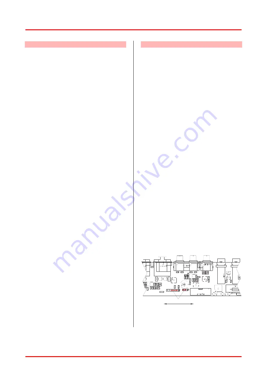
12.2. Pre Out Setting
Internal jumpers are provided to assign Pre or
Post Master Pre Out setting.
Thanks this internal setting it is possible to adjust
the Pre Out level by the Master control or make it
independent, following the system requirements.
From the factory, Pre Master setting is assigned.
The figure Fig6. shows the instructions to assign
the Pre Out Setting.
PRE / POST
Fig6.
Pre Out Internal Adjustment


