191
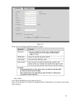
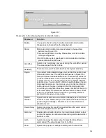
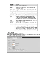
Parameter
Function
Server Type
You can select DDNS protocol from the dropdown list and then
enable DDNS function.
Server IP
DDNS server IP address
Server Port
DDNS server port.
Domain Name
Your self-defined domain name.
User
The user name you input to log in the server.
Password
The password you input to log in the server.
Update period
Device sends out alive signal to the server regularly.
You can set interval value between the device and DDNS server
here.
Please go to the corresponding service website to apply a domain name and then access the system via
the domain. It works even your IP address has changed.
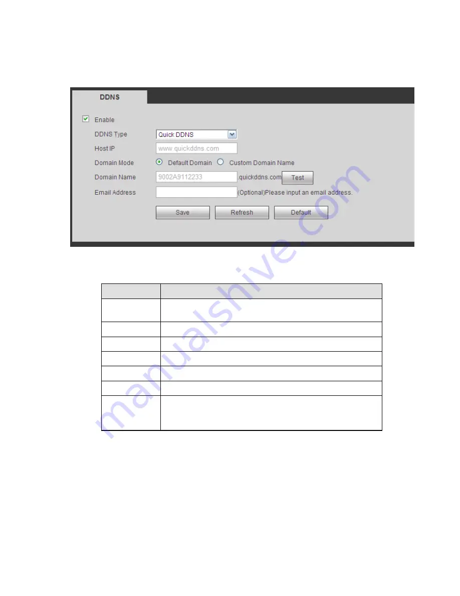
Please select DDNS from the dropdown list (Multiple choices). Before you use this function, please make
sure your purchased device support current function.
Figure 5-33
Please refer to the following sheet for detailed information.
Quick DDNS and Client-end Introduction
1) Background Introduction
Device IP is not fixed if you use ADSL to login the network. The DDNS function allows you to access the
NVR via the registered domain name. Besides the general DDNS, the quick DDNS works with the device
from the manufacturer so that it can add the extension function.
2) Function Introduction
The quick DDNS client has the same function as other DDNS client end. It realizes the bonding of the
domain name and the IP address. Right now, current DDNS server is for our own devices only. You need
to refresh the bonding relationship of the domain and the IP regularly. There is no user name, password
or the ID registration on the server. At the same time, each device has a default domain name (Generated
by MAC address) for your option. You can also use customized valid domain name (has not registered.).
Summary of Contents for NVR-3202K
Page 1: ...i NVR 3202K User manual ...
Page 20: ...9 ...
Page 29: ...18 Figure 3 1 ...
Page 83: ...113 Figure 4 71 Figure 4 72 ...
Page 84: ...114 Figure 4 73 Figure 4 74 ...
Page 90: ...120 Figure 4 79 Figure 4 80 ...
Page 91: ...121 Figure 4 81 Figure 4 82 ...
Page 92: ...122 Figure 4 83 Figure 4 84 ...
Page 94: ...124 Figure 4 86 Figure 4 87 ...
Page 132: ...162 Figure 4 132 Figure 4 133 4 14 3 1 Add Modify Group ...
Page 172: ...202 The motion detect interface is shown as in Figure 5 52 Figure 5 52 Figure 5 53 ...
Page 173: ...203 Figure 5 54 Figure 5 55 Figure 5 56 ...
Page 177: ...207 Figure 5 60 Figure 5 61 ...


