background image


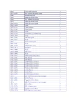
2.2  Connector Summary


Summary Table


Nbr


Description


Type of Connections


Pin nbrs.


J1


CF Master/Slave Switch


Slide Switch


On/OFF


J3


USB


External USB Connector


6-pin


J4


USB


External USB Connector


6-pin


J5


USB (Touchscreen)


2.0mm 5-pin wafer


5-pin


J6


J-TAG


1.25mm 6-pin wafer


6-pin


J8


PS/2 Keyboard


2.54mm 5-pin box header


5-pin


J9


PS/2 Keyboard/Mouse


External Mini DIN Socket


6-pin


J10


COM1(RS232/422/485)


External D-Sub Male Connector


9-pin


J14


VGA


2.0mm 10-pin box header


10-pin


J27


LVDS connector


1.25mm WAFER20P


20-pin


J18


Micro SD Card Socket


Micro SD socket


9-pin


J24


Audio Mic-In


2.0mm 4-pin wafer


4-pin


J29


Power/IDE LED


2.0mm 4-pin wafer


4-pin


RJ45


Ethernet


External RJ45 Connector


8-pin


PWR


Power Connector (5A)


External Mini DIN Socket


3-pin


PWR


Power Connector (8A)


External Power Plug


2-pin


J23


Audio Line-Out


1.25mm Phone Jack


CF1


CF Card Socket


CF Type I/II Socket


J13


Mini-PCI Socket


Expansion Mini-PCI Socket


J18


Micro SD Card Socket


Micro SD socket


Summary of Contents for PTDX5311

Page 1: ...PTDX5311 PTDX9211 User s Manual...

Page 2: ...umes no responsibility for any inaccuracies that may be contained in this document And makes no commitment to update or to keep current the information contained in this manual No part of this manual...

Page 3: ...servicing Never touch un insulated terminals or wire unless your power adaptor is disconnected Locate your Panel PC as close as possible to the socket outline for easy access and to avoid force caused...

Page 4: ...Ordering Information 5 1 5 Packing List 5 C h a p t e r 2 System Installation 6 2 1 CPU Board Outline 6 2 2 Connector Summary 8 2 3 Connector Pin Assignments 9 2 4 External I O Overview 12 2 5 Externa...

Page 5: ...This page is blank v...

Page 6: ...integrated 10 100M Ethernet port supplies the communication capability which makes PTDX5311 9211 can be more widely used when running with Linux Windows CE and Windows XP environment to become the pe...

Page 7: ...Audio CM119 Line Out Internal Drives Compact Flash Type I II slot Micro SD slot I O RS 232 422 485 x 1 USB ports Ver2 0 x 2 RJ 45 Port x 1 Expansion Slot Mini PCI socket x 1 Internal Mechanical Enviro...

Page 8: ...st Ratio 500 1 Display Color 262 144 Pixel Pitch mm 190 5 H x 189 V PTDX9211 Viewing Angle Vertical 110o Horizontal 140o Backlight Lifetime 25 000 hrs Touchscreen Type Analog Resistive Resolution Cont...

Page 9: ...1 3 Product...

Page 10: ......

Page 11: ...C h a p t e r 2 System Installation 2 1 CPU Board Outline Bottom View...

Page 12: ...10 COM1 RS232 422 485 External D Sub Male Connector 9 pin J14 VGA 2 0mm 10 pin box header 10 pin J27 LVDS connector 1 25mm WAFER20P 20 pin J18 Micro SD Card Socket Micro SD socket 9 pin J24 Audio Mic...

Page 13: ...e J3 USB Pin Signal Name Pin Signal Name 1 VCC 2 USBD2 3 USBD2 4 GND 5 GND 6 GND J4 USB Pin Signal Name Pin Signal Name 1 VCC 2 USBD3 3 USBD3 4 GND 5 GND 6 GND J5 USB Touchscreen Pin Signal Name 1 VCC...

Page 14: ...2 MSCLK 3 GND 4 KBDATA 5 MSDATA 6 VCC 7 GND 8 GND 9 GND J10 COM1 RS232 422 485 Change setting by BIOS Pin Signal Name Pin Signal Name 1 DCD1 422TX RS485 2 RXD1 422TX RS485 3 TXD1 422RX 4 DTR1 422RX 5...

Page 15: ...IGHTNESS 5 TXOUT0 6 TXOUT0 7 TXOUT1 8 TXOUT1 9 GND 10 GND 11 TXOUT2 12 TXOUT2 13 TXCLKOUT 14 TXCLKOUT 15 GND 16 GND 17 5V 18 5V 19 NC 20 NC J24 MIC IN Pin Signal Name 1 MICVREF 2 GND 3 GND 4 MIC IN PW...

Page 16: ...PWR Power Connector 8A Pin Signal Name 1 8 35V 2 GND J29 Power IDE LED Pin Signal Name 1 PWRLEDP 2 PWRLEDN 3 IDELEDP 4 IDELEDN...

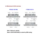
Page 17: ...2 4 External I O Overview PTDX5311 9211WA PTDX5311 9211A Note1 Wireless is optional Note2 COM1 RS232 422 485 is selected by BIOS setting...

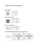
Page 18: ...Connector 5A Pin Signal Name 1 5V 2 GND 3 NC Power Connector 8A Pin Signal Name 1 8 35V 2 GND J10 COM1 RS232 422 485 Change setting by BIOS Pin Signal Name Pin Signal Name 1 DCD1 422TX RS485 2 RXD1 4...

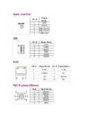
Page 19: ...uch 4 Open Touch 5 VREFOUT USB Pin Signal Name 1 VCC 2 USB0 3 USB0 4 GND 5 GGND 6 GGND RJ45 Pin Signal Name Pin Signal Name 1 FTXD 2 FTXD 3 FRXIN 4 NC 5 NC 6 FRXIN 7 NC 8 NC PS 2 Keyboard Mouse Pin Si...

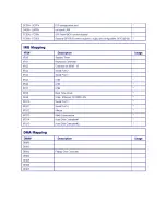
Page 20: ...2 6 System Mapping...

Page 21: ......

Page 22: ......

Page 23: ...2 7 Watchdog Timer There are two watchdog timers in PTDX5311 9211 we also provide DOS Linux and WinCE example for your reference...

Page 24: ...media detection AUDIO CM119 is a highly integrated single chip USB audio controller specifically for VoIP Voice over internet protocol application All essential analog modules are embedded in CM119 i...

Page 25: ...dded and Windows 2000 installation note 1 Please visit Vortex86DX CPU website to get more information ftp ftp asm cz XtendLan RB_TC 261DX_261HDX_261LDX_262DX_DXM Manual RB_TC_26xDX_MX_Debian_5 pdf 2 G...

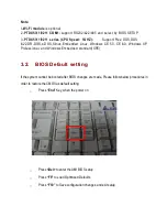
Page 26: ...ndows CE 5 0 CE 6 0 Windows XP Professional and Windows Embedded standard XPE 3 2 BIOS Default setting If the system cannot be booted after BIOS changes are made Please follow below procedures in orde...

Page 27: ...ons accident or disaster Vendor assumes no liability for any damages lost profits lost savings or any other incidental or consequential damage resulting from the use misuse of originality to use this...

Reviews: