background image


40 


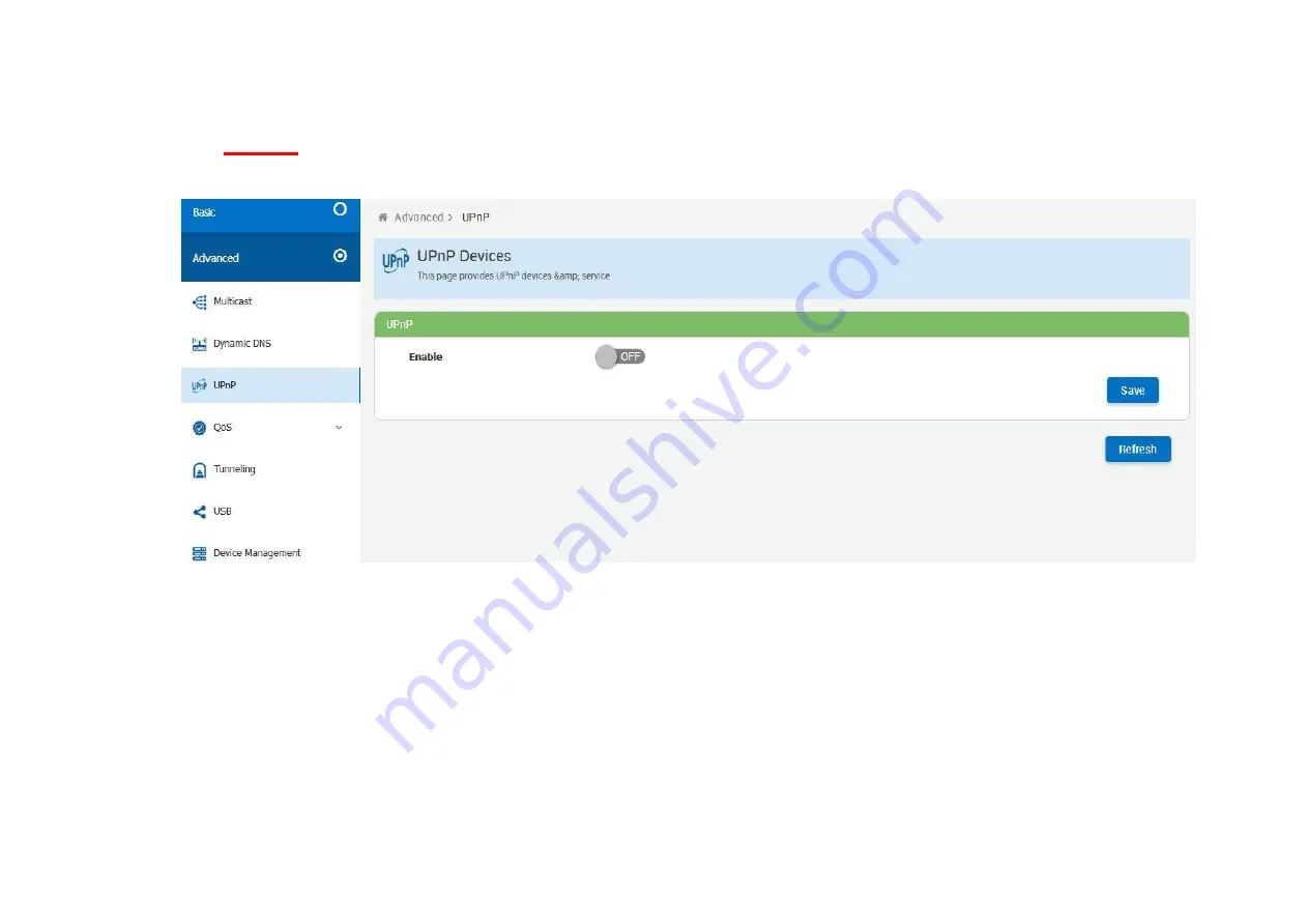
4.3.3 

UPnP 

This page provides UPnP devices & service. 


Figure 4.3.3 UPnP


Summary of Contents for XL-GFC142M

Page 1: ...XL GFC142M G fast Master Modem XL GFC142SR G fast VDSL2 V35b Slave Modem Router USER S MANUAL...

Page 2: ...install nor use your device during a thunderstorm There may be a remote risk of electric shock from lightning DO NOT expose your device to dampness dust or corrosive liquids DO NOT use this product ne...

Page 3: ...4 Configure the modem via Web managementmenu 21 Appendix A Cable Requirements 46 Appendix B Product Specifications Key Features Benefits 50 Appendix C Troubleshooting 53 This is a class A product In a...

Page 4: ...2V 2A Power Adapter 1x Power cord 1 Please inform your dealer immediately for any missing or damaged parts If possible retain the carton including the original packing materials Use them to repack the...

Page 5: ...ent physical space and proximity to other network devices that are to be connected Verify the following installation requirements Power requirements DC 12 V 2A orabove The modem should be located in a...

Page 6: ...11 Terminal block combo All network connections to the RJ 11 terminal block sharing port must use 24 26 gauge with single twisted pair phone wire We do not recommend the usage of the other gauge phone...

Page 7: ...This may damage the modem Instead use only twisted pair cables withRJ 45 connectors that conform to Ethernet standard Notes 1 Be sure each twisted pair cable RJ 45 Ethernet cable does not exceed 100...

Page 8: ...oint application First a quick overview on a complete setup of LAN extender Master Slave LAN extender XL GFC142 is a LAN extender leverages the extraordinary bandwidth promise of G fast technology max...

Page 9: ...with or without noise injection and crosstalk simulations 2 5 2 Connect the XL GFC142M DPU Master and the XL GFC142SR CPE Slave to LAN Devices In the setup usually an Ethernet tester serves as a repr...

Page 10: ...12 2 6 Internet ISP application...

Page 11: ...13 2 7 CCTV application...

Page 12: ...14 Chapter 3 Hardware Description This section describes the important parts it features the front panel and rear panel Physical appearance...

Page 13: ...ady indicates firmware Model as XL GFC142M and LED Off indicates firmware Model as XL GFC142SR 2 If want to change DPU to CPE Model just update firmware to right mode The reverse is also do the same s...

Page 14: ...power good Off The device is not ready or has malfunctioned LED Color Status Descriptions E1 E4 Ethernet LED Green On Steady The device has a good Ethernet connection Blinking The device is sending or...

Page 15: ...nection is up Fast Blinking The Master device has detected a Slave device and ready to connect Off The Internet or network connection is down Master Green On Steady Device firmware on XL GFC142M DPU M...

Page 16: ...he modem rear connectors Type Connector Description Reset Tact Switch Button The reset buttons allows users to reboot the device or load the default settings Press and hold for 1 5 seconds Reboot devi...

Page 17: ...s must cross make sure the wires are perpendicular at the intersection point Note You can use the type of signal transmitted through a wire to determine which wires should be kept separate The rule of...

Page 18: ...ote 1 Default factory model shown as back sticker inclusing default model name S N FCC CE Mark Input DC voltage information User s maunal download QR code made of origin default LAN IP and web managem...

Page 19: ...der to use the web browser to configure the device you may need to allow Web browser pop up windows from your device Web pop up blocking is enabled by default in windows XP SP2 or above Java Scripts E...

Page 20: ...20 4 1 BASIC Setup 4 1 1 Login Webpage The default username and password are admin Figure 4 1 1 Login Webpage...

Page 21: ...play status When the device is running the status page will display the device informations Internet Status Software Version and DSL Line Status etc as shown in Figure 4 1 2 XL GFC142M 1 Figure 4 1 2...

Page 22: ...22 XL GFC142SR Figure 4 1 2 Device Info...

Page 23: ...Basic There is an easy Setup for end users at the setup of XL GFC142M with G fast LAN System Routing and XL GFC142SR with WAN Internet DSL LAN System Routing for more detail configurations Figure 4 2...

Page 24: ...24 4 2 1 WAN Internet This page allows you to view and configure various Internet connections Figure 4 2 1 WAN Internet information...

Page 25: ...ious DSL Modes Provides configuration for xDSL G fast modes and upstream downstream attributes XL GFC142M DPU provides G fast mode configuration for customized untilization which you can simply select...

Page 26: ...ation Using this technique the line is more tolerant of errors caused by noise and signal loss As the parameters are adjusted the bandwidth may be markedly decreased if there is a large amount of line...

Page 27: ...27 The default settings for the XL GFC142SR are as follows Figure 4 2 2 1 Mode Setting...

Page 28: ...28 4 2 1 2 Status This page provides the various status and statistics information Figure 4 2 2 2 Status...

Page 29: ...3 Configuration Configuration support to provide IP address to devices connected on the LAN side of the CPE Applicable for all wired and wireless devices that requests for dynamic IP address Figure 4...

Page 30: ...30 4 2 1 4 Devices Connected List of Clients Connected on the LAN Side of the device Figure 4 2 3 2 Devices Connected...

Page 31: ...4 System 4 2 1 5 Administration This page allows users to take configuration backup restore to previous configuration or to factory settings upgrade firmware and reboot device Figure 4 2 4 1 Administ...

Page 32: ...32 4 2 1 6 User Management Configure new users with add delete and modify options Figure 4 2 4 2 User Management...

Page 33: ...33 4 2 1 7 System Time Configuration to enable the device to synchronize the system time with the time servers Figure 4 2 4 3 System Time...

Page 34: ...34 4 2 1 8 Diagnostics Allows to perform diagnosis on various sub systems of this device Figure 4 2 4 4 Diagnostics...

Page 35: ...35 4 2 5 Routing Web Page to Add Delete Static Route in the System Figure 4 2 5 Static Routing...

Page 36: ...low will be used frequently XL GFC142M includes the sub menus of UPnP USB SATA Device Management XL GFC142SR includes the sub menus of Multicast Dynamic DNS UPnP QoS Tunneling USB SATA Device Manageme...

Page 37: ...37 XL GFC142SR Figure 4 3 Advanced...

Page 38: ...38 4 3 1 Multcast This page allows to configure the Multicast services Figure 4 3 1 Multcast...

Page 39: ...9 4 3 2 Dynamic DNS Dynamic DNS allows the user to update wan IP address with one or many dynamic DNS services So anyone can access services on computer using DNS like address Figure 4 3 2 Dynamic DNS...

Page 40: ...40 4 3 3 UPnP This page provides UPnP devices amp service Figure 4 3 3 UPnP...

Page 41: ...Quality of Service QoS settings enables you to manage and optimize the performance of the applications It shapes the network traffic and prioritizes the devices and services by controlling the bandwid...

Page 42: ...42 Figure 4 3 4 QoS...

Page 43: ...6rd is a mechanism to facilitate IPv6 rapid deployment across IPv4 infrastructures of Internet service providers ISPs DSLite is a mechanism to facilitate IPv4 deployment across IPv6 infrastructure Fig...

Page 44: ...44 4 3 6 USB SATA Always ensure that you click on the Safe Remove button to safely remove respective USB SATA storage devices Figure 4 3 6 USB SATA...

Page 45: ...45 4 3 7 Device Management Device Management allows to view and configure parameters relating to the device s association with an ACS Figure 4 3 7 Device Management...

Page 46: ...sion The connector at the end of the 1000TX cable is referred to as a RJ 45 connector and it consists of eight pins The Ethernet standard uses pins 1 2 3 4 5 and 6 for data transmission purposes Table...

Page 47: ...47 Figure A 2 Pin Assignments and Wiring for an RJ 45 Straight Through Cable Figure A 3 Pin Assignments and Wiring for an RJ 45 Crossover Cable...

Page 48: ...plain old telephone services use pins 3 and 4 for voice transmission A telephone cable is shown below Figure A 4 A B Figure A 4 Telephone cable The A and B connectors on the rear of the Modem are RJ 1...

Page 49: ...bps Support USB 3 0 for connecting USB Dongle Support static routing for IPv4 and IPv6forwarding XL GFC142SR only Support 8 queue MFC DSCP both type QoS Support HTTP HTTPS web management Support SSL s...

Page 50: ...e port 1 x RJ 11 connector for POTS ISDN phone device 1 x Reset Button for resetting to factory default 2 x USB3 0 for connecting USB dongle 1 x Power LED 4 x Link Active Status for Ethernet port 1 x...

Page 51: ...l load with 2 x USB port Power Supply Input Voltage 12V DC Operating Temperature 0 C 50 C Storage Temperature 0 C 50 C Humidity 10 to 90 non condensing Dimensions 196 x 146 x 40 mm Weight 0 4 kg EMC C...

Page 52: ...fail to resolve the problem have the unit power supply replaced by a qualified distributor 2 Symptom Devices can t handsharking after making aconnection Network interface ex a network adapter card on...

Page 53: ...e reinsert power when change cable length or link time over 3minutes 3 4 If CPE connect to IP DSLAM and link failure please try to change band profile as 17a for getting long reach Phone wire must mee...

Page 54: ...example from Static Routing Destination LAN IP 0 0 0 0 Subnet Mask 0 0 0 0 Gateway 192 168 16 1 Note Static Routing functionality is used to define the connected Gateway between the LAN and WAN 6 Ques...

Reviews: