background image

                                                                                                                                                                         TR6.55  Treadmill                   


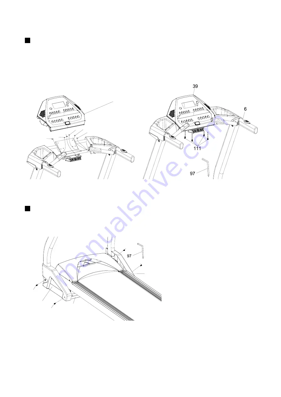
  STEP 5 

36 25

112-3

26

39

27

27


  STEP 6 


44

111

111

111

111

43

2


Connect all six connectors to the mating connectors on the back of the console. There are two 

3-pin connectors that are color coded, make sure to plug them into the correct place. There are 

two 2-pin connectors that can be plugged into either mating connector on the console. Secure 

the console (39) to the console frame with four M5 X 15mm screws (111). Tighten using the 

Combination M5 Allen Wrench & Phillips Head Screw Driver (97). 

Attach the left (44) and right (43) covers to the upright base frame with four M5 X 15mm 

screws (111). Tighten using the Combination M5 Allen Wrench & Phillips Head Screw Driver (97).

Summary of Contents for TR6.55

Page 1: ...OWNER S MANUAL ...

Page 2: ...n 2 Important Safety Instructions 3 Important Electrical Information 4 Important Operation Instructions 5 Assembly instructions 6 Operation of Your New Treadmill 10 General Maintenance 19 Manufacturer s Limited Warranty 23 Table of Contents ...

Page 3: ...act in the future We appreciate your confidence in Xterra and we will always remember that you are the reason that we are in business Please complete and mail your registration card today and enjoy your new treadmill Yours in Health The folks at Xterra Fitness Name of Dealer______________________________________ Telephone Number of Dealer___________________________ Purchase Date___________________...

Page 4: ...vious pinch points and other caution areas that can cause harm Keep hands away from all moving parts Never operate the treadmill if it has a damaged cord or plug If the treadmill is not working properly call your dealer Keep the cord away from heated surfaces Do not operate where aerosol spray products are being used or where oxygen is being administered Sparks from the motor may ignite a highly g...

Page 5: ...Examples Grainger part 1D237 or available online at www squared com part QO120HM This product must be grounded If the treadmill s electrical system should malfunction or breakdown grounding provides a path of least resistance for electric current reducing the risk of electric shock This product is equipped with a cord having an equipment grounding plug The plug must be plugged into an appropriate ...

Page 6: ...t up Simply standing on the belt during slow acceleration is proper after you have learned to operate the unit ALWAYS hold on to a handrail or hand bar while making control changes incline speed etc A safety tether cord is provided with this unit It is a simple magnetic design that should be used at all times It is for your safety should you fall or move too far back on the tread belt Pulling this...

Page 7: ...ST 111 M5 x 15mm Phillips Head Screw 12pcs 95 5 16 x 19mm Curved Washer 4pcs 94 5 16 x 15mm Button Head Socket Bolt 14pcs 102 Safety Key 1pc 93 Lubricant 1pc 97 Combination M5 Allen Wrench Phillips Head Screw Driver 1pc 98 M6 Allen Wrench 1pc 110 5 16 x 19mm Flat Washer 10pcs ...

Page 8: ... 5 38 94 95 94 4 5 97 2 95 94 1 Feed the long twist tie that is attached to the computer cable from the base frame 38 through the right side upright tube 5 and slide the tube into the base frame tube Be careful not to pinch the wire harness washers 110 for the side bolts and two 5 16 curved washers 95 for the front bolts ...

Page 9: ... frame to the right 5 and left 4 uprights with six 5 16 bolts 94 and 5 16 flat washers 110 Tighten using the Combination M5 Allen Wrench Phillips Head Screw Driver 97 2 Install the fan assembly 112 to the underside of the console frame with the four M5 X 15mm screws 111 Tighten using the Combination M5 Allen Wrench Phillips Head Screw Driver 97 3 Go back and securely tighten the eight 5 16 bolts 9...

Page 10: ...nto the correct place There are two 2 pin connectors that can be plugged into either mating connector on the console Secure the console 39 to the console frame with four M5 X 15mm screws 111 Tighten using the Combination M5 Allen Wrench Phillips Head Screw Driver 97 Attach the left 44 and right 43 covers to the upright base frame with four M5 X 15mm screws 111 Tighten using the Combination M5 Alle...

Page 11: ...ower is turned on a message will scroll across the dot matrix showing the current software version Then the Time and Distance windows will display Odometer readings for a short time Time window will show how many hours the treadmill has been in use and the Distance window will show how many miles or Kilometers if the treadmill is set to metric readings the treadmill has gone The treadmill will the...

Page 12: ...lorie readings will hold while the unit is in the pause mode After 5 minutes the display will reset and return to the start up screen STEP 2 To resume your exercise when in Pause mode press the Start key The speed and incline will return to their previous settings Pause is executed when the Stop button is pressed once If the Stop key is pressed a second time the program will end and a workout summ...

Page 13: ...ing each one for five seconds 1 4 mile Track The 1 4 mile track will be displayed around the dot matrix window The flashing dot indicates your progress Once the 1 4 mile is complete this feature will begin again The number of completed laps is displayed in the Laps window Pulse Grip Feature The Pulse Heart Rate readout will display your current heart rate in beats per minute during the workout You...

Page 14: ... You may press start at any time during the programming to start the program STEP 3 The Calorie window will now be displaying a value which is your Body Weight Entering the correct body weight will affect the calorie count Use the Up Down keys Fast Slow to adjust then press enter A note about the Calorie display No exercise machine can give you an exact calorie count because there are too many fac...

Page 15: ...TR6 55 Treadmill 14 XTERRA TR6 55 TREADMILL PROFILES ...

Page 16: ... you in control of the machine s speed instead of the machine controlling you Selecting a Heart Rate Control Program You have the option during the setup mode to choose either the Weight Control HR 1 program or the Cardiovascular HR 2 program The Weight Control program attempts to maintain your heart rate at 60 of your Maximum Heart Rate The Cardiovascular program attempts to maintain your heart r...

Page 17: ...s you of proper operation If you wish you may wear the transmitter over a shirt To do so wet the areas of the shirt that the electrodes will rest upon Note The transmitter is automatically activated when it detects activity from the user s heart Addition ally it automatically deactivates when it does not receive any activity Although the transmitter is water resistant moisture can have the effect ...

Page 18: ... training for the heart and lungs and weight control The black columns on the chart above represent the Maximum Heart Rate for a person whose age is listed at the bottom of each column The heart rate training zone for either cardiovascular fitness or weight loss is represented by two different lines which cut diagonally through the chart A definition of the lines goal is in the bottom left hand co...

Page 19: ...rception of Effort 6 Minimal 7 Very very light 8 Very very light 9 Very light 10 Very light 11 Fairly light 12 Comfortable 13 Somewhat hard 14 Somewhat hard 15 Hard 16 Hard 17 Very hard 18 Very hard 19 Very very hard 20 Maximal You can get an approximate heart rate level for each rating by simply adding a zero to each rating For example a rating of 12 will result in an approximate heart rate of 12...

Page 20: ...UG POWER CORD BEFORE THIS TASK BELT ADJUSTMENTS Tread belt Tension Adjustment Belt tension is not critical for most users It is very important for joggers and runners in order to provide a smooth steady running surface Adjustment must be made from the right side of the rear roller in order to adjust tension with the 6 mm Allen wrench provided in the parts package The adjustment bolt is located at ...

Page 21: ...ncern as the belt is used Proper belt tracking is an owner responsibility common with all treadmills ATTENTION DAMAGE TO THE RUNNING BELT RESULTING FROM IMPROPER TRACKING TENSION ADJUSTMENTS IS NOT COVERED UNDER THE XTERRA WARRANTY ENGINEERING MODE If you want to set the Speed and Distance to Metric or if there is a problem with the speed and you would like to perform the calibration procedure use...

Page 22: ... the same amount of turns and also remember how many turns because when finished you will need to tighten the bolts back to the point they were before Once the belt is loose wipe the deck with a clean lint free cloth to remove any dirt Apply the whole tube of lubricant onto the deck surface about 18 inches from the motor cover Squeeze out the contents of the tube across the deck parallel to the mo...

Page 23: ...responsive Display is lit Make certain clock is running If it is then service may be Needed Treadmill will only achieve approximately 7 mph but shows higher speed on display This indicates motor should be receiving power to operate Low AC voltage to treadmill Do not use an extension cord If an extension cord is required it should be as short as possible and heavy duty 16 gauge minimum Low househol...

Page 24: ...terations modifications abuse misuse accident improper maintenance inadequate power supply or acts of God 4 Products with original serial numbers that have been removed or altered 5 Products that have been sold transferred bartered or given to a third party 6 Products that are used as store display models 7 Products that do not have a warranty registration on file at Xterra Fitness inc Xterra Fitn...

Reviews: