background image

Page 18

ChASSIS TUNING GUIDE

The Rail features front, centre and rear bevel gear differentials that feature O-Ring seals and cup-style housings. All three differentials 
are packed with differential grease that works well for most driving conditions. You can make fine-tuned adjustments to each differential 
by removing them from the chassis, opening them up and replacing the grease with different weights of silicone oil.

l


Front and Rear Differentials:

 Adding heavier silicone oil will tighten the differentials and adding lighter silicone oil will loosen the 

differentials. If your Rail feels loose (uncontrollable) during turns, you can tighten the front differential or loosen the rear differential. If 
your Rail is pushing (understeer) during turns, you can loosen the front differential or tighten the rear differential.

l


Centre Differential: 

Using a lighter weight oil will cause the differential to unload easier. Generally, this is good for loose tracks with 

little traction. Using a heavier weight oil will provide a more even amount of power to the front and rear. On loose tracks, this can 
cause the Rail to be too 'squirrely' (uncontrollable) or cause the rear end to slide out. For this reason, we only suggest using heavier 
oil if you're driving on a high-traction surface.

n  

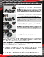
Adjusting the Differentials - Front, Centre, and Rear

q

   Remove the upper hinge pins, then remove the screws that hold the upper suspension 

plate in place.

q

   Remove the upper and lower suspension plates, then firmly pull the front half of the 

differential case straight out.

We detail below the removal of the front differential. Removing the centre and rear differentials is similar. If necessary, refer to the 
Exploded View Assembly Drawings beginning on page 28 for more detailed information.

recommended Initial settings

l

  Unless you're racing, we recommend initially using the grease that already fills each differential. For general dirt track racing, we 

recommend using the following weights of differential oils: 3K in the Front, 10K in the Centre, and 2K in the Rear. For use in the sand, 
we recommend using 30K in the Front, 70K in the Centre and 10K in the Rear.

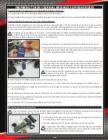
q

   Remove the hinge pins, drop the lower suspension arms, then firmly pull the 

differential assembly straight out.

q

   Remove the four 2 x 10mm self-tapping screws that hold the differential housing 

together. Pull the differential housing apart, then pull the differential assembly out of 
the differential housing.

q

   You can now disassemble the differential, remove the grease, then reassemble and 

refill the differential with the silicone oil of your choice.

For detailed information about disassembling, then re-assembling the differentials, 
see the 'STEP 1: FRONT, REAR, AND CENTRE DIFFERENTIALS' section on page 28.

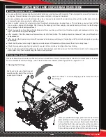
q

   Remove the two 4 x 12mm self-tapping screws and the two 4 x 16mm self-tapping 

screws from the bottom of the chassis that hold the front bumper and front half of 
the gearbox in place, then remove the front bumper.

When reinstalling the front bumper after filling the differential, make sure to install 
the two longer 4 x 16mm self-tapping screws in the front half of the gearbox and 

the two shorter 4 x 12mm self-tapping screws in the front bumper.

Summary of Contents for RAIL

Page 1: ...Page 1 Kit Product 145633 U S C XTM RAILBL Europe ...

Page 2: ...ent is well protected with the custom aluminium roll cage and side frames which are secured together to provide a rigid and stable chassis Supporting the Rail are threaded aluminium coil over oil filled shocks at each corner which soak up the terrain with ease for a smooth ride With the adjustable steel gear differentials adjustable suspension geometry and optional sand paddle tyres the Rail is su...

Page 3: ...d the safety of others prior to making any programming changes to the Electronic Speed Controller using the included ESC programming card we strongly suggest removing the pinion gear from the motor This will prevent any chance of a runaway model l The tyres on your model will balloon to a larger diameter when mounted on a high speed model such as the Rail Brushless Off Road Buggy DO NOT hold the m...

Page 4: ...ries to be exposed to moisture l DO NOT short circuit Li Po batteries l DO NOT leave Li Po batteries plugged into your model when not in use Li Po batteries should be stored in a fire proof container l ALWAYS let Li Po batteries cool between uses and charging l INSPECT Li Po batteries before each use for swelling or other malformation If damaged they should not be used l DO NOT poke bend or otherw...

Page 5: ...the ESC will be damaged In addition NEVER mix Ni Cd Ni MH or Li Po cells Regardless of the type of battery pack s you choose the following pertains the more cells you use the more power the battery pack will provide but the heavier the battery pack will be The higher the capacity of the battery pack e g mAh the longer the run time you will experience but the heavier the battery pack will be Whilst...

Page 6: ...Hs or 2 4S Li Pos In addition the ESC features a 3 Amp 6 Volt Battery Eliminator Circuit BEC forward and reverse control and a cooling fan that helps keep the ESC from getting too hot The ESC can also be programmed using the included ESC programming card Brushless Motor with Heat Sink and Cooling Fans The brushless motor provides the power to the drivetrain Brushless motors are more efficient and ...

Page 7: ...ood for most off road applications The wheels are moulded in one piece from lightweight high impact plastic and feature a metal outer ring for extra strength Wing Provides downforce to ensure maximum traction Wing angle can be adjusted to suit different track conditions n Chassis Component Overview Continued bECOmING fAmILIAR WITh YOUR RAIL bRUShLESS Off ROAD bUGGY n Brushless Power System Overvie...

Page 8: ...eaded into nylon or composite material need only be tightened snugly l If you have difficulty sliding the receiver antenna wire through the antenna support tube first pull the antenna wire through your fingers several times to straighten it then lightly wet the antenna wire with glass cleaner The glass cleaner will make the antenna wire slide through the support tube much easier Leave any excess a...

Page 9: ... unsnap the spacer block from the back of the battery holder and remove it Otherwise leave this spacer block in place The majority of 6 cell Ni MH battery packs and 2S Li Po battery packs will fit without the need to remove the spacer block q Slide your battery pack into the battery holder then pull the two battery retaining straps tight to hold your battery pack securely in place Install your bat...

Page 10: ...of each other without interfering with the battery leads If using two hard case Li Po car battery packs with the battery connectors in the top of the battery unsnap the spacer block from the back of the battery holder and reinstall it at the front of the battery holder This will allow the batteries to be installed staggered with the battery connectors toward the back of the battery holder Install ...

Page 11: ...en release the SET button The Status LED is visible through the side frame near the bottom of the ESC q Pull the throttle trigger to full throttle The red LED will flash then the red LED will turn solid and the ESC will beep once q Push the throttle trigger to full reverse The orange LED will flash then the orange LED will turn solid and the ESC will beep twice q Rotate the transmitter s wheel for...

Page 12: ...e The following ESC options can be customised l Low Voltage Cutoff l Running Mode l Motor Timing l Initial Acceleration l Reverse Throttle Limit l Throttle Limit l Braking Percentage l Drag Brake Percentage l Operating Hertz l Neutral Range This section describes basic ESC programming procedures For more detailed information including information about each of the customisable options please refer...

Page 13: ...g the ESC throttle lead from the receiver q Plug the ESC throttle lead into the prog card connector on the ESC programming card observing correct polarity the white signal wire should be toward the outside of the ESC programming card as indicated To make changes to the different programming options follow the procedures below q Press the MENU button to cycle through the various menus 1 10 The curr...

Page 14: ...grees toe in on the front and 2 degrees toe in on the rear for overall best 4WD driveability on most surfaces 2 degrees toe in on the rear is stock q To adjust the toe in on the rear tyres use one of the different suspension holders provided to set the desired toe angle as described in the procedures below For convenience the degree of toe angle is moulded into the back of each suspension holder q...

Page 15: ... camber adjustments use a dedicated camber gauge available at most hobby retailers By adjusting the spring tension of the shocks you can increase steering sensitivity adjust the ride height of the Rail and fine tune the damping quality of the suspension system How you drive your Rail will dictate what settings you should be using As an example if you re driving your Rail off road and going over lo...

Page 16: ...the outside will make the shock stiffer and moving the shock toward the inside will make the shock softer You will need to experiment with these settings to find something that suits both your track and driving style A good starting point is to adjust the rear shocks Moving the rear shocks toward the outside will give more bite traction in the turns However depending on how you drive you might wan...

Page 17: ...he servo saver adjustment ring in the factory position q To access the servo saver spring remove the steering servo linkage from the servo arm then remove the steering servo by removing the four 3 x 10mm self tapping screws from the bottom of the chassis that hold the two servo mounts in place q Adjust the servo saver spring by adjusting the servo saver adjustment ring up or down Threading the adj...

Page 18: ... the front half of the differential case straight out We detail below the removal of the front differential Removing the centre and rear differentials is similar If necessary refer to the Exploded View Assembly Drawings beginning on page 28 for more detailed information recommended Initial settings l Unless you re racing we recommend initially using the grease that already fills each differential ...

Page 19: ...n the pinion gear and the spur gear If you re using either of the XTM Racing 12T 13T or 14T pinion gears the gear mesh is set correctly based on the particular motor mounting holes you install the motor into If using other brand pinion gears you may have to experiment with the mounting hole positions After adjusting the position of the motor you will need to pivot the motor heat sink so that the t...

Page 20: ...pressed air apply several drops of lubricating oil to the motor bearings to ensure top performance l Check that the wheel nuts are tight Applying a small amount of threadlock will help prevent them from coming loose l Check the suspension and steering system to ensure both are working smoothly without any binding l If you re using the optional foam filter over the motor heat sink fans periodically...

Page 21: ...o 4 x 10mm machine screws that secure the motor and centre differential assembly in place Pull the motor and centre differential up and out of the chassis Unplug the motors wires from the ESC then unplug the two motor heat sink fans from the Y Harness adapter Unplug the throttle channel lead from the receiver then pull it out from below the motor heat sink fans A B C Continued On Next Page ...

Page 22: ...ICK bREAK DOWN GUIDE Remove the two 3 x 6mm machine screws that hold the ESC to the side frame Unplug the motor wires from the ESC then unplug the Y Harness from the motor heat sink fans Next unplug the throttle channel lead from the receiver Pull the ESC up and out of the chassis A C B Continued On Next Page ...

Page 23: ...ing the Battery holder mAINTENANCE AND qUICK bREAK DOWN GUIDE Remove the four 3 x 10mm self tapping screws from the bottom of the chassis that hold the battery holder in place Pull the battery holder up and out of the chassis A B Continued On Next Page ...

Page 24: ...WN GUIDE Remove the two 3 x 8mm machine screws from the bottom of the chassis that hold the receiver mounting box in place Pull the receiver mounting box up and out of the chassis Remove the receiver box lid then unplug the steering servo and throttle channel leads from the receiver B Continued On Next Page A C ...

Page 25: ...6mm self tapping screws from the bottom of the chassis that hold the rear suspension assembly in place Remove the 3 x 20mm machine screw and the lock nut that hold the front of the rear suspension mounting brace in place Pull the rear suspension assembly along with the rear centre dog bone up and off the chassis A C B A Continued On Next Page ...

Page 26: ...ering knuckles Remove the two 4 x 12mm self tapping screws and the four 4 x 16mm self tapping screws from the bottom of the chassis that hold the front bumper and the front suspension assembly in place Remove the 3 x 15mm self tapping screw that holds front chassis brace to the front chassis cross brace Pull the front suspension assembly along with the rear centre dog bone out and off the chassis ...

Page 27: ...pinion gear A Vibration under normal use A Servo saver spring too loose A Transmitter throttle channel reversing incorrect B Motor wires swapped A ESC programmed for forward only operation B Incorrect throttle use A Batteries not connected properly A ESC Braking Percentage not adequately set A Throttle control range not calibrated B Throttle channel EPA out of adjustment A Readjust trim to centre ...

Page 28: ...16 x 5mm 6 148623 Shim 8 x 12 x 0 4mm 3 148602 Flat Head Tapping Screw 3 x 16mm 12 148570 Grub Screw w Threadlock 4 x 4mm 3 for front rear and centre x3 for front and rear x2 for centre x1 differential oil differential oil 149895 149895 149895 149895 149895 149895 Sub 1 149895 149895 149895 148570 149899 149563 149893 149899 149563 148602 148623 148602 149897 149905 149895 149895 149905 148764 148...

Page 29: ...10mm 8 148572 Grub Screw w Threadlock 5 x 4mm 2 149563 Ball Bearing 8 x 16 x 5mm 2 148593 148593 149778 Step 1 Step 2 149918 149563 149317 148572 finished 148583 Button Head Tapping Screw 3 x 38mm 2 148675 149911 Step 3 149911 ExPLODED vIEW ASSEmbLY DRAWINGS 148583 for front and rear x2 Continued On Next Page ...

Page 30: ...m 8 x 12 x 0 2mm 2 149506 148566 149505 148566 149505 149563 149343 148624 149305 148574 149563 149305 149506 STEP 5 FRONT SHOCK TOWER 148558 Lock Nut 3mm 4 148576 Button Head Tapping Screw 3 x 10mm 1 148511 Cap Screw 3 x 25mm 2 148506 Cap Screw 3 x 16mm 4 148676 148506 148506 Step 4 148558 148558 finished for right and left sides x2 ExPLODED vIEW ASSEmbLY DRAWINGS Sub 5 148576 148511 148671 14930...

Page 31: ... SUSPENSION ARMS AND AXLES ExPLODED vIEW ASSEmbLY DRAWINGS 148567 Grub Screw 4 x 10mm 2 148613 Button Head Screw w Threadlock 4 x 20mm 2 8 8mm 148706 148707 148707 149491 148692 148692 Step 7R Step 7L Step 6L 148613 148613 148613 148613 148695 148695 Step 7L for right side for left side Step 6R Step 7R Continued On Next Page ...

Page 32: ...ton Head Tapping Screw 4 x 8mm 2 148583 Button Head Tapping Screw 3 x 38mm 2 Step 5 149915 Step 8L Step 8R right side left side ExPLODED vIEW ASSEmbLY DRAWINGS 148584 Button Head Tapping Screw 4 x 12mm 2 148584 148558 149901 148648 148674 148615 Step 3 148583 149911 149911 148615 148674 148559 Lock Nut 4mm 1 148507 Cap Screw 4 x 50mm 1 149907 148559 148693 148507 Continued On Next Page ...

Page 33: ... ExPLODED vIEW ASSEmbLY DRAWINGS STEP 11 WING MOUNT 148581 Button Head Tapping Screw 3 x 18mm 4 149271 Post 6 x 32mm 2 149271 149271 148581 149271 149271 149271 148581 148558 Lock Nut 3mm 4 148559 Lock Nut 4mm 1 Sub 12 148559 Step 11 148511 148649 Step 10 148558 148558 148511 148677 148694 148576 149307 Sub 12 Continued On Next Page ...

Page 34: ...DED vIEW ASSEmbLY DRAWINGS 148574 Grub Screw w Threadlock 5 x 5mm 2 149305 Pin 2 5 x 16 8mm 2 148624 Shim 8 x 12 x 0 2mm 2 149563 Ball Bearing 8 x 16 x 5mm 4 for left side for right side 149381 Hub Stud 43 5mm 2 149301 149483 149563 149305 148574 149305 148624 149483 149563 149543 149493 149497 149497 149543 13 2mm Sub 14 148558 148533 Step 13 149381 148558 149291 148567 for right and left sides x...

Page 35: ...xPLODED vIEW ASSEmbLY DRAWINGS 148566 Grub Screw w Threadlock 3 x 3mm 2 148570 Grub Screw w Threadlock 4 x 4mm 2 148601 Flat Head Tapping Screw 3 x 12mm 4 148542 Flat Head Screw 3 x 20mm 2 Step 10 Step 14R 148584 149915 149901 Step 14L 150036 148566 Sub 16 149293 149293 149293 149293 149293 Sub 16 Step 15 149293 149293 148601 148570 148601 148509 148560 Sub 16 148542 for right and left sides x2 Co...

Page 36: ...Y DRAWINGS 148578 Button Head Tapping Screw 3 x 12mm 1 148559 Lock Nut 4mm 1 148507 Cap Screw 4 x 50mm 1 148601 Flat Head Tapping Screw 3 x 12mm 8 148559 Step 9 148578 148697 148507 148676 148680 148680 148676 148601 148601 148601 148680 148601 148601 148676 148601 148676 148680 148688 148689 Continued On Next Page ...

Page 37: ...readlock 4 x 10mm 2 ExPLODED vIEW ASSEmbLY DRAWINGS STEP 20 STEERING TIE RODS for right and left sides x2 149331 Turnbuckle 4 x 48mm 2 148558 148558 Step 18 R 148690 148548 148539 148548 148558 148539 148558 148539 Step 18L 148558 148670 149549 149331 148670 149549 30 5mm 149455 149455 Continued On Next Page ...

Page 38: ...rew 3 x 20mm 2 149567 Bushing 6 x 10 x 3mm 4 149559 Flanged Ball Bearing 5 x 8 x 2 5mm 2 149457 Servo Saver Screw 3 x 19 7mm 2 149567 149455 149453 149453 149455 149455 149567 149567 149453 149567 149457 148558 148691 148625 149559 149559 149457 148558 148625 Sub 21 Step 20 148509 148558 148558 148509 Step 20 Sub 21 Sub 21 Continued On Next Page ...

Page 39: ...8 148509 Cap Screw 3 x 20mm 8 148576 Button Head Tapping Screw 3 x 10mm 2 148525 Button Head Screw w Threadlock 3 x 8mm 2 148527 Button Head Screw w Threadlock 3 x 12mm 4 148509 149863 150040 Sub 22A Sub 22A 149859 148699 Step 1 Sub 22C 148576 148525 148527 148667 148669 148570 145651 Sub 22B Sub 22A x2 Sub 22B Sub 22C 148702 Continued On Next Page ...

Page 40: ... 45mm 2 148661 Shock Body 14 x 53mm 2 148660 148661 O Ring 12 4 x 1 78mm 4 3 5mm 3 5mm 3 0mm 3 x 1mm 3 5mm 3 5mm 3 0mm 3 x 1mm 149840 149840 149840 149840 149840 148660 148660 149850 149850 149899 149850 148660 149942 148660 149841 149841 149841 149841 149841 148661 148661 149850 149850 149899 149850 148661 149942 for front x2 one 3mm o ring is Installed Between two 3 5mm o rings and one 3 x 1mm o...

Page 41: ...ly Pump shaft up and down several times to Eliminate Air Bubbles for front and rear x4 149850 148660 148661 Step 23 STEP 25 SHOCK SPRINGS 148672 Shock Spring 58 x 1 6mm Silver 2 148673 Shock Spring 80 5 x 1 6mm Silver 2 for front x2 for rear x2 Step 24 149850 148672 149850 148673 149312 Step 24 149312 Continued On Next Page ...

Page 42: ...ed Lock Nut 3mm 2 148542 Flat Head Screw 3 x 20mm 2 right side left side STEP 27 REAR SHOCK MOUNTING 148560 Flanged Lock Nut 3mm 2 148542 Flat Head Screw 3 x 20mm 2 right side left side 149347 148560 Step 25 148542 Step 17 149347 148560 Step 25 148542 Step 16 Continued On Next Page ...

Page 43: ...GS 148576 Button Head Tapping Screw 3 x 10mm 6 148600 Flat Head Tapping Screw 3 x 10mm 4 148548 Flat Head Screw w Threadlock 4 x 10mm 2 148607 Flat Head Tapping Screw 4 x 12mm 2 148576 148698 149884 149884 148576 148576 Sub 28 Step 22 Step 19 148600 148607 148548 Sub 28 ST CH1 Continued On Next Page ...

Page 44: ...ASSEmbLY DRAWINGS STEP 29 FRONT SUSPENSION MOUNTING 148607 Flat Head Tapping Screw 4 x 12mm 2 148598 Flat Head Tapping Screw 4 x 16mm 4 149984 Sub 29 Step 26 148696 Step 28 148607 148598 148598 Sub 29 Continued On Next Page ...

Page 45: ... 148627 Button Head Screw 3 x 20mm 2 148659 Button Head Screw 3 x 22mm 2 148554 Washer Head Screw w Threadlock 4 x 10mm 2 148579 Button Head Tapping Screw 3 x 15mm 1 148621 Shim 6 x 9 8 x 0 2mm 2 148579 148554 148558 148703 148627 148621 Step 21 148627 Step 29 148659 148659 Continued On Next Page ...

Page 46: ...SUSPENSION MOUNTING 148558 Lock Nut 3mm 1 148542 Flat Head Screw 3 x 20mm 1 148598 Flat Head Tapping Screw 4 x 16mm 4 ExPLODED vIEW ASSEmbLY DRAWINGS Step 27 Step 30 148542 148598 148598 149791 148558 Continued On Next Page ...

Page 47: ...Page 47 ExPLODED vIEW ASSEmbLY DRAWINGS STEP 32 BATTERY HOLDER INSTALLATION 148600 Flat Head Tapping Screw 3 x 10mm 4 150039 148668 Sub 32 148600 148600 148600 Step 31 Sub 32 Continued On Next Page ...

Page 48: ...LODED vIEW ASSEmbLY DRAWINGS STEP 33 Electronic Speed Controller MOUNTING 148529 Button Head Screw 3 x 6mm 2 145652 148529 Step 32 A B C BLACk Red YeLLow double Sided Tape Continued On Next Page BLue YeLLow oRAnge ...

Page 49: ...ni MH Battery 6C Li Po Battery 2S ni MH Battery 6C Brushless Motor A B C Black Red Yellow neg neg PoS PoS PoS neg white neutral Red Positive Black negative Steering Servo CH 1 on off Switch Brushless eSC CH 1 CH 2 CH 3 BATT CH 2 ST TH Step 22 Step 32 149851 For Fan 6V Receiver Continued On Next Page ...

Page 50: ...crew 3 x 18mm 1 148560 Flanged Lock Nut 3mm 1 148527 Button Head Screw w Threadlock 3 x 12mm 1 ExPLODED vIEW ASSEmbLY DRAWINGS 148527 149312 148670 149333 149333 148558 149333 148508 Step 33 Sub 35 148560 Servo Arm Included with Servo Retaining Screw Included with Servo Sub 35 Continued On Next Page ...

Page 51: ...8526 Button Head Screw 3 x 15mm 2 150042 Post 6 x 19mm 2 148576 Button Head Tapping Screw 3 x 10mm 4 148546 Flat Head Screw w Threadlock 3 x 8mm 2 149860 149860 148708 149860 148576 Sub 36A 148526 148526 148708 150042 148546 148546 Step 35 Sub 36A Sub 36B Sub 36B Receiver Continued On Next Page ...

Page 52: ...n Push the Antenna support tube into the Antenna mount in the top of the receiver Box tighten the Knurled Nut finger tight to secure do Not cut any Excess Antenna shorter Allow any Excess Antenna wire to hang out Beyond the End of the Antenna support tube Step 36 Receiver Step 36 Antenna Support Tube Continued On Next Page ...

Page 53: ...148546 Flat Head Screw w Threadlock 3 x 8mm 4 STEP 39 REAR CENTRE ROLL BAR 148582 Button Head Tapping Screw 3 x 8mm 4 148546 148684 148678 148678 148684 148546 148546 148546 148582 148582 Sub 39 Step 38 148679 148582 148686 148679 148582 Sub 39 Continued On Next Page ...

Page 54: ...8505 Cap Screw w Threadlock 3 x 10mm 2 STEP 41 ROOF PLATE 148576 Button Head Tapping Screw 3 x 10mm 4 148582 Button Head Tapping Screw 3 x 8mm 2 148677 148677 148682 148677 148677 148582 Step 39 148505 148505 Sub 40 148576 148576 148681 Step 40 Sub 40 Continued On Next Page ...

Page 55: ...Page 55 ExPLODED vIEW ASSEmbLY DRAWINGS STEP 42 ROLL BAR POSTS 148582 Button Head Tapping Screw 3 x 8mm 6 Step 41 148685 148582 148687 148582 148683 148582 Continued On Next Page ...

Page 56: ...ODED vIEW ASSEmbLY DRAWINGS STEP 43 ROLL BAR MOUNTING 148558 Lock Nut 3mm 2 148582 Button Head Tapping Screw 3 x 8mm 6 148582 Step 42 148582 148582 148558 148558 148582 148582 148582 Step 36 Continued On Next Page ...

Page 57: ...the tyre wheel It s Important that the tyre is securely Affixed to the wheel for right and left sides x4 148665 148665 148664 outside Inside C A Tyre glue not Included STEP 45 WHEEL RINGS 148502 Button Head Screw 3 x 6mm 24 for right and left sides x4 148502 148502 148710 Step 44 Continued On Next Page ...

Page 58: ... STEP 46 WHEELS BODY AND WING MOUNTING ExPLODED vIEW ASSEmbLY DRAWINGS 149303 Wheel Nut 17mm 4 right side left side 149319 149319 149319 149319 149319 148709 149554 149321 149303 Step 45 Step 43 Step 45 149303 ...

Page 59: ...51 Brushless Motor 2370kV 145652 Brushless ESC 120A 2 4S 6 12C 148621 Servo Saver Shims 6x9 8x0 1mm Qty 10 148624 Differential Shims 8x12x0 2mm 148623 Differential Shims 8x12x0 4mm 148625 Differential Shims 8x12x0 8mm Qty 10 Qty 10 Qty 10 148660 Shock Body Set Front L 45mm 148661 Shock Body Set Rear 148662 Shock Assemblies Front 1 6mm Silver L 108mm L 53mm Qty 2 148663 Shock Assemblies Rear 1 6mm ...

Page 60: ...8681 Roof Plate 148682 Roll Bar Front Centre L 130mm 148683 Roll Bars Centre Side L 56 8mm Qty 2 148684 Roll Bars Main 148685 Roll Bars Rear Upper 148686 Roll Bar Rear Centre 148687 Roll Bars Rear Side L 274mm L 40 2mm L 80mm L 89mm Qty 2 Qty 2 Qty 2 148689 Side Guard Right 148688 Side Guard Left 2mm 6061 2mm 6061 148690 Chassis 3mm 6061 148691 Servo Saver Steering Plate 3mm 6061 148692 Balls 4x10...

Page 61: ...48710 Wheel Rings Silver Aluminium Qty 2 148726 Decal Set 148764 Spur Gear 53T 148891 Differential Assembly Front or Rear 148892 Differential Assembly Centre 53T Spur Gear 149271 Wing Mount Set 149291 Suspension Arms Lower Rear Qty 2 149293 Sway Bar Set 2 8mm 149301 Wheel Shafts Rear Qty 2 L 43mm 149303 Wheel Nuts Front and Rear 149305 Hex Hubs Front or Rear Qty 4 17mm Silver 149307 Shock Mounting...

Page 62: ...ht and Left Qty 2 149491 Turnbuckles 5mm Upper Front L 25mm Qty 2 149493 Turnbuckles 5mm Upper Rear L 36mm Qty 2 149497 Suspension Arms Upper Rear Qty 4 149505 CVD Universal Joints Front 149506 CVD Universal Joint Rebuild Kit L 125mm Qty 2 149543 Balls 7x3mm Steel Qty 4 149549 Steering Ball Link Ends L 22 5mm Qty 4 149554 High Downforce Wing Black 149563 Ball Bearing 8x16x5mm 149567 Bushings 6x10x...

Page 63: ...e 149897 Differential Ring Gear 43T Straight Cut Use with 149898 149898 Differential Pinion Gear 13T Straight Cut Use with 149897 149899 O Rings 3x1mm Qty 10 149901 Hinge Pins Lower L 67 5mm Qty 4 149905 Gaskets for Differentials Qty 5 149907 Wing Mount Stabiliser Rod 149911 Gearbox Halves Front or Rear 149915 Upper Suspension Holders 0º 3º 149918 Differential Housing Assembly with Aluminium Cover...

Page 64: ...10mm Qty 5 148554 Washer Head Screw with Threadlock 4 x 10mm Qty 5 148600 Flat Head Tapping Screw 3 x 10mm Qty 10 148601 Flat Head Tapping Screw 3 x 12mm Qty 10 148602 Flat Head Tapping Screw 3 x 16mm Qty 10 148607 Flat Head Tapping Screw 4 x 12mm Qty 10 148598 Flat Head Tapping Screw 4 x 16mm Qty 10 148582 Button Head Tapping Screw 3 x 8mm Qty 10 148576 Button Head Tapping Screw 3 x 10mm Qty 10 1...

Page 65: ...ium 148712 Wheel Rings Green Aluminium Qty 2 Qty 2 Qty 2 148714 6 Shot Wheels Light Silver Qty 2 148715 6 Shot Wheels Smoke Silver Qty 2 148716 Sand Paddle Tyres with Inserts 148722 Sand Paddle Tyres on 6 Shot Wheels Qty 2 Qty 2 Front or Rear Black 148733 Wheel Rings Gold Aluminium 148732 Wheel Rings Smoke Silver Aluminium Qty 2 Qty 2 149259 Wheel Nuts 17mm Black Qty 4 149261 Hex Hubs Front or Rea...

Page 66: ...ty 4 Qty 4 150106 Closed End Wheel Nuts Silver 150107 Closed End Wheel Nuts Black 17mm 17mm n Power System Accessories and Gearing Affects Power and Acceleration 145795 Battery Jumper 4mm Short L 102mm for 5mm Shaft 148718 Motor Pinion Gear 12T Steel use with 149862 for 5mm Shaft 149849 Cooling Fan Filter Foam 150031 Motor Pinion Gear 13T Steel n 100 Silcone Oils For Tuning Differentials and Shock...

Page 67: ...Blue 40Lbs 149355 Dust Boots for Shock Shafts Qty 4 Qty 4 Qty 4 Qty 4 Qty 4 n Shock Absorbers and Shock Absorber Springs Affects Ride Quality and Handling 149318 Shock Spring Set Front 4 Pair 1 4mm 1 5mm 1 6mm 1 7mm L 58mm 149320 Shock Spring Set Rear 4 Pair 1 4mm 1 5mm 1 6mm 1 7mm L 80 5mm 149349 Shock Springs Front 1 7mm Black L 58mm Qty 2 149350 Shock Springs Front 1 6mm Yellow L 58mm Qty 2 149...

Page 68: ...s Rear Replaces 149491 L 25mm Replaces 149493 L 36mm Qty 2 Qty 2 149591 Shock Tower 5mm 7075 Front Replaces 148671 149991 Suspension Holder 7075 Front Replaces 149915 149275 Upper Suspension Plate Front 3mm 6061 Black Replaces 148675 148719 Aluminium Chassis Brace Rear Replaces 148693 n Shock Absorbers and Shock Absorber Springs Affects Ride Quality and Handling Continued 149364 Shock Springs Rear...

Page 69: ... Metric Hex Wrench Set 1 5mm 2 0mm 2 5mm 3 0mm 149520 Bi Level Wing White 149521 Bi Level Wing Yellow 149909 Ball Ends 3 5mm for 7mm Ball L 25 5mm Qty 4 149861 Antenna Mount Blue 148727 Body Shell Clear w Decals 148723 Body Shell Printed with Decals Red Carbon Qty 5 n Anodised Aluminium Side Guard and Roll Cage Options Changes Appearance 150061 Side Guard Right Blue 150070 Side Guard Right Red 150...

Page 70: ... 150086 Roll Bars Centre Side Green 150087 Roll Bars Centre Side Smoke Silver 150122 Roll Bars Centre Side Gold L 56 8mm L 130mm 150123 Roll Bar Front Centre Blue 150089 Roll Bar Front Centre Red 150124 Roll Bar Front Centre Gold 150091 Roll Bar Front Centre Smoke Silver 150090 Roll Bar Front Centre Green Qty 2 150125 Roll Bar Rear Centre Blue 150092 Roll Bar Rear Centre Red 150093 Roll Bar Rear C...

Page 71: ...plies permission for Global Services Ripmax Ltd to service your model at our discretion l Include a method of payment for any service charges l Send the unit to us by United Parcel Service Federal Express or by Insured Mail Postage is nonrefundable Send your package to In North America Global Services 18480 Bandilier Circle Fountain Valley CA 92708 Phone 714 963 0329 Fax 714 964 6236 Email service...

Page 72: ...Page 72 Features and Specifications are Subject to Change Without Notice All contents 2010 XTM Racing and Global Hobby Distributors All Rights Reserved Revision 1 09 15 2010 Made in Taiwan ...

Reviews: