background image

Operation Manual

4

XR5519

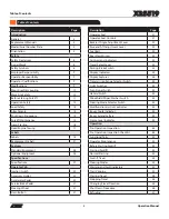
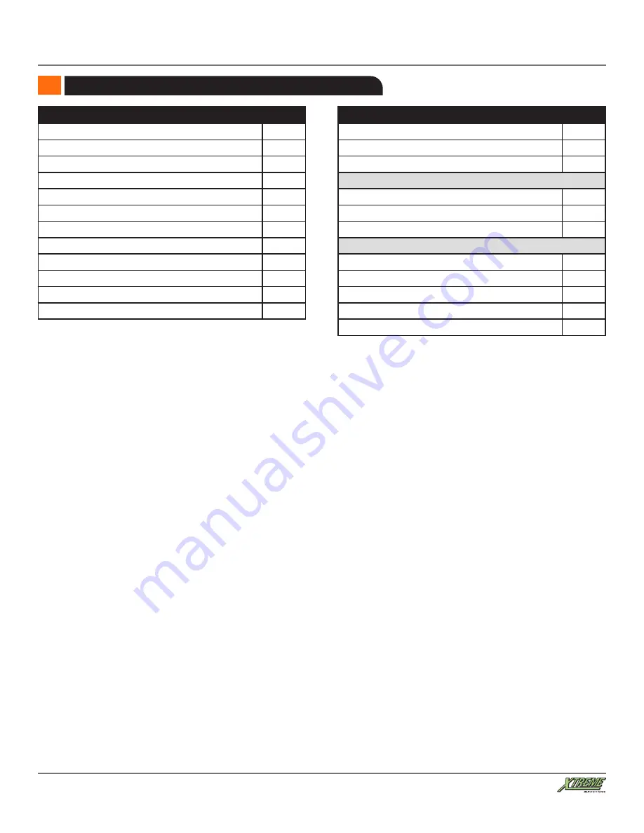
Table of Contents

Table of Contents

Description

Page

Fuel Types

57

Winter Operation With Diesel Fuel 

57

Attachments

58

Attachment Disclaimer

58

Fork Ratings

58

Standard Carriage Operation

59

Quick Attach System

59

Load Handling

62

Boom Lift Point

63

Suspended Loads

63

Pick Up a Load

63

Carry a Load

64

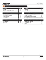
Description

Page

Place a Load

64

Load Shift

64

Load Capacity Charts

64

Preventive Maintenance

Establishing a Maintenance Program

66

Maintenance Schedule

66

Boom Emergency Lower Down Valve

68

Lockout / Tagout

Do Not Operate -  Accident Prevention Tags

70

New or Additional Operators

70

Lockout/Tagout Procedure

70

Do Not Operate Tags

71

Warranty

72

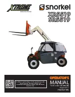
Summary of Contents for Snorkel XR5519

Page 1: ...157 0070 000 MANUAL OPERATOR S OPERATOR S XR5519 Pre delivery Inspection Report must be completed upon plac ing unit in service Please use QR link or visit www xmfg com warranty pre delivery inspectio...

Page 2: ...s well as a global sales distribution network Snorkel Europe Limited Snorkel USA LLC and Snorkel New Zealand Limited are wholly owned by Snorkel International Holdings LLC whose mem bers are Xtreme Ma...

Page 3: ...utton 31 Table of Contents Description Page Operator Seat 31 Operator Seat Controls 31 Backrest Angle Adjustment Lever 32 Fore and Aft Adjustment Lever 32 Seat Belt 32 Rear View Mirrors 33 Controls an...

Page 4: ...59 Load Handling 62 Boom Lift Point 63 Suspended Loads 63 Pick Up a Load 63 Carry a Load 64 Description Page Place a Load 64 Load Shift 64 Load Capacity Charts 64 Preventive Maintenance Establishing...

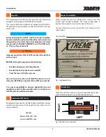
Page 5: ...and rear are directional references given from the operator s seat when facing forward Fig 2 Forklift Direction Orientation Warning Notice FRONT REAR RIGHT LEFT General Replacement Manuals Model Seria...

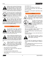
Page 6: ...afety Disclaimer CAUTION Yellow with the safety alert symbol indicates a potentially hazardous situation which if not avoided could result in minor or moderate injury Caution Caution Warning Safety Sy...

Page 7: ...ate If Using Alcohol Drugs Or Medications Personal Protective Equipment Safety Shoes Lead Acid Batteries Create Explosive Gases Warning Hydraulic Oil Under Pressure Hot Oil DO NOT Open Unless Cap Is C...

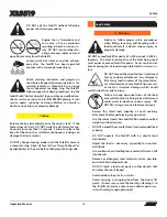
Page 8: ...ke To ON Engage Parking Brake Warning Forklift Tip Over Can Cause Death Or Serious Injury DO NOT Raise Boom While Traveling On A Slope Danger Keep A Safe Distance From Electrical Lines Pinch Points Ha...

Page 9: ...ation or alter ation including welding or drilling can im pair and weaken the protective capability of the Rollover Protective Structure Falling Object Protective Structure ROPS FOPS and could result...

Page 10: ...s 2 Electrical cables 3 Sewers Underground objects could cause death or serious in jury Warning Operate the forklift only on firm stable surfaces Holes obstructions debris loose fill and other work si...

Page 11: ...ctions and functional tests may require assistance Keep the assistant visible and a safe distance from the forklift to prevent death or serious injury Become familiar with all safety and hazard labels...

Page 12: ...rk site operating directives and or local or state codes might require a greater distance Know the maximum height and reach of this forklift Warning Use of the frame sway control with the boom raised...

Page 13: ...n before shifting to the next lower gear Improper use of the gear select lever could cause transmission damage or forklift tip over roll over and result in death or serious in jury Operate the forklif...

Page 14: ...nd traveling with a load could result in death serious injury or property damage DO NOT exceed forklift capacity of 5 500 pounds 2 494 ki lograms The total rated capacity of the forks being used must...

Page 15: ...required Forklift Maintenance Warning Follow the manufacturer s instructions for proper maintenance to make sure the forklift continues to meet manufacturer s specifications Failure to properly maint...

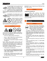
Page 16: ...a to cause cancer birth defects or other reproductive harm Wash hands after Warning handling these items California Proposition 65 Warning Wear eye protection when connecting jump start cables Imprope...

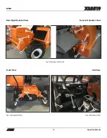
Page 17: ...arking brake then stop Fig 3 Parking Brake Screw Location At The Front Of The Front Axle Re Activating Parking Brakes Front Axle Warning Block all four wheels Failure to do so could result in death or...

Page 18: ...8 XR5519 Labels Labels Left Side View Right Side View Fig 5 Label Legend Left Side Fig 6 Label Legend Right Side 24 9 32 10 13 10 16 36 14 3 INNER BOOM 37 23 Labels 36 30 9 23 37 8 34 10 12 19 7 26 S...

Page 19: ...R5519 Labels Labels Rear Right Quarter View Cab View Fig 9 Label Legend Cab Rear Left Quarter View Fig 7 Label Legend Rear Left 15 18 2 21 38 20 10 Front View 10 35 35 Fig 8 Label Legend Front 34 35 1...

Page 20: ...OTATING EQUIP MENT 20 1 18031 001 LABEL WARNING CHECKLIST 21 1 18032 001 LABEL WARNING IMPROPER USE 22 5 18041 100 LABEL WARNING PINCH POINT 23 1 18082 100 LABEL WARNING INJECTION HAZ ARD 24 1 18083 1...

Page 21: ...4 Please have the appropri ate label number available when you call Replacement Labels 1 18008 000 3 18010 100 5 18013 002 DIESEL ONLY 18013 002 Ultra Low Sulphur Fuel Only Maximum Sulphur Content 15p...

Page 22: ...Operation Manual 22 XR5519 Labels 7 18015 001 8 18016 100 18016 100 11 18018 002 12 18019 100 18019 100 9 18017 001 10 18018 100 18018 100...

Page 23: ...Operation Manual 23 XR5519 Labels 13 18020 100 18020 100 14 18021 100 18021 100 17 18025 100 18025 100 18 18026 100 18026 100 15 18022 001 16 18023 001...

Page 24: ...Operation Manual 24 XR5519 Labels 18082 100 18083 100 19 18027 001 20 18031 001 22 18041 100 18041 100 21 18032 001 WARNING 23 18082 100 24 18083 100...

Page 25: ...Operation Manual 25 XR5519 Labels 18086 100 18090 100 27 18090 100 25 18086 100 18086 101 26 18086 101 28 18043 000 29 18044 000 30 18046 000 31 18047 000 32 18048 000...

Page 26: ...Operation Manual 26 XR5519 Labels 18315 000 40 18315 000 18314 000 39 18314 000 38 18312 000 35 18232 000 37 18300 001 18400 003 33 18049 000 34 18400 003 36 18233 000...

Page 27: ...shutting engine off before setting the battery disconnect switch to OFF Equipment damage may occur if the engine control systems are not allowed to shutdown properly 43 18412 000R01 18408 001 AUX CON...

Page 28: ...ch Screen Display Easy access drop down electrical panel 12 Volt accessory power outlet Electric horn and backup alarm Rear view mirror Adjustable seat with seat belt Boom angle indicator Tires Air fi...

Page 29: ...lbs Power Train Engine Deutz 74 hp Fuel Capacity 26 gal Transmission Hydrostatic Brakes Inboard Wet Disc Parking Brake SAHR Tires Tires Standard Eq Air Filled 12 50 x 18 Hydraulics GPM 26 PSI 3 200 Hy...

Page 30: ...nition Switch Position Purpose OFF Shuts down entire electrical system except the horn and accessory outlet RUN All controls and indicators are operable START Engages starter motor to crank engine NOT...

Page 31: ...e front 2 wheels Fig 13 Service Brake Pedal Steering Wheel Turn the steering wheel left or right to steer the forklift in the corresponding direction Fig 14 Steering Wheel Horn Button Press the horn b...

Page 32: ...efective it may not properly restrain the operator which could result in death or serious injury DO NOT operate the forklift until the seat belt or mounting hardware is replaced if worn or damaged The...

Page 33: ...ositions FORWARD NEUTRAL and REVERSE which change the direction of travel Fig 21 Travel Select Lever Controls and Indicators Travel Select Lever Position Purpose F Forward UP Position away from the op...

Page 34: ...ved to the RUN position Wait until the indicator goes out before starting the engine F ENGINE SHUTDOWN The Engine Shutdown Indicator will be displayed when there is a serious engine fault and the engi...

Page 35: ...Indicator Chart H HIGH HYDRAULIC OIL TEMP The hydraulic oil temperature indicator illuminates when the oiltemperatureisabove1800F Ifthehydraulicoiltemperature indicator illuminates stop and idle the e...

Page 36: ...splay allows the operator to view vital engine information and other critical functions including gauge display engine diagnostics to monitor engine condition and performance fault codes and warning l...

Page 37: ...t Log to view the new events Touching the button returns to the previous screen whereas the X button will close the menu MEASURE Select Measure and then scroll down through this menu to view the statu...

Page 38: ...s that can be accessed by the user at this time allow for adjusting the rotation speed of the drilling auger and are displayed in the Boom Auxiliary Group Scroll down to this option and select it to e...

Page 39: ...AVAILABLE SETTINGS OPTIONS Background The background themes are displayed on a drop down list The selected background theme is displayed in the top right corner of the screen High Tech background sele...

Page 40: ...the ENGINE button at the bottom of the main screen Fig 45 CAN Switches CAN Switches Touching the CAN Switches opens the Master Switch cluster display which allows for viewing the status of the Steerin...

Page 41: ...ted load chart attached to the front control console the load chart can be viewed on screen by selecting the Labels option and then navigating to the available load charts Fig 52 On Screen Load Chart...

Page 42: ...urn signals left or right Fig 56 Turn Signal Switches Left and Right Fig 57 Hazard Switch Hazard Switch Optional If equipped with this option the Strobe Light Switch turns on ans off the strobe light...

Page 43: ...to the axle before changing steering mode Changing steering modes at higher travel speeds can make the forklift unstable and cause a loss of control which could result in death serious injury or prope...

Page 44: ...accomplished with the label 18408 001 affixed right below the joystick for easy reference The Joystick Enable button needs to be depressed in order for the joystick to be operational This avoids unint...

Page 45: ...ner of the operator s cab The frame level indicator allows the operator to view if the forklift has been positioned in a level condition Fig 65 Frame Level Indicator Boom Maintenance Stand Optional Th...

Page 46: ...If the seat belt or mounting hardware is defective it may not properly restrain the operator resulting in death or serious injury DO NOT operate the forklift until the seat belt or mount ing hardware...

Page 47: ...e of California to cause cancer birth defects or other reproductive harm Wash hands after Warning handling these items California Proposition 65 Warning Wear eye protection when starting a forklift wi...

Page 48: ...tion inspection Check that Do Not Operate tags have not been placed on the forklift Check that load capacity charts are legible Check mirrors for cracks cleanliness and proper adjustment Check engine...

Page 49: ...ft should stop immediately Apply the parking brake The forklift should not move unless the parking brake is released Test each steering function Operate the forklift in forward and reverse at low spee...

Page 50: ...agent concentration can be checked with conventional test instruments e g re fractometer At temperatures below 41 C please contact your local Xtreme Manufacturing or DEUTZ partner 70F 180F 310F 420F W...

Page 51: ...ry Check the battery the case and the battery terminals Warning Lead acid batteries produce flammable and potentially ex plosive gases To avoid death or serious injury when check ing testing or chargi...

Page 52: ...isengaging a control DO NOT jump from the forklift Clothing can get caught on pedals levers or other protrudingparts Landingonunevensurfaces could result in death or serious personal injury Before sta...

Page 53: ...g can damage the starter motor 3 Turn key in ignition switch clockwise to the START position You may need to hold the key in this position for a few seconds before the engine begins to crank see NOTE...

Page 54: ...modes Crab steering allows all four 4 wheels to turn in the same direction as the steering wheel allowing the forklift to move sideways Crab steering is useful in a congested work site to line up to...

Page 55: ...ing above 500 RPM Low Oil Pressure Warning below 10 psi Rear Axle Centered Rear Axle Locked Service Reminder Transmission Temperature Indicator between 215 and 224 0F Transmission Temperature Warning...

Page 56: ...njury or property damage Changing Travel Direction 1 Stop the forklift by applying the service brake pedal 2 Move travel select lever to FORWARD F or REVERSE R 3 Release the service brake pedal 4 Slow...

Page 57: ...st and some of its constituents are known by the State of California to cause cancer birth defects or other reproductive harm California Proposition 65 Warning Winter Operation With Diesel Fuel Specia...

Page 58: ...eed forklift capacity Forks can bend or break causing loss of load and could result in death or serious injury All approved forks for this forklift are marked with a maximum load capacity rating A Thi...

Page 59: ...ury Attachments not locked into place could become unstable and fall on the operator or other personnel near the forklift which could result in death or serious injury Make sure attachment locking dev...

Page 60: ...Fig 78 Insert Quick Attach Pin Through Attachment and Quick Attach Adapter Fig 79 Quick Attach Pin Keeper 7 Insert quick attach pin keeper Hydraulic attachments have a maximum hydraulic pressure rati...

Page 61: ...ilt the attachment backward 6 Disconnect the quick attach couplers this only applies to attachments with a quick attach hydraulic system Fig 81 Disconnect Quick Attach Couplers Fig 82 Remove Quick Att...

Page 62: ...ds in excess of the manufactur er s rated load may cause forklift tip over loss of load or structural damage which could re sult in death serious injury or property damage Warning Review the rated loa...

Page 63: ...ly steadying the load The handling of suspended loads can introduce dynamic forces drastically affecting the stability of the forklift Grades and sudden starts stops and turns can cause the load to sw...

Page 64: ...what angle how high and how for to extend the boom NOTE For example when letter A first appears the boom extension corresponds to the arc of line A throughout all the load capacity charts The boom ang...

Page 65: ...use death se rious injury or property damage The frame sway feature becomes locked and will not operate when the boom is raised 40 or more Applying service brake parking brake and placing travel selec...

Page 66: ...nsion meter to check belt tension Lubricate front and rear driveshaft grease fittings Lubricate front and rear axle grease fittings Check wheel lug nuts torqued to 250 ft lbs Lubricate boom pivot poin...

Page 67: ...xle wheel end and differential oil clean magnetic drain plugs After Every 1 000 Hours of Operation Comply with 50 Hour Maintenance Requirements Comply with 250 Hour Maintenance Requirements Comply wit...

Page 68: ...position where it can be removed safely completely remove the load from the carriage and or attachment Otherwise leave the load in place 5 Remove boom access cover on back of boom Fig 94 Boom Access...

Page 69: ...or of the lift lower section on the proportional control valve first section from boom side on top of the valve and use it to manually operate the valve to lower the boom Be aware of lowering the boom...

Page 70: ...f this vehicle is to be used by an employee or is loaned or rented to someone other than the purchaser make certain that the new operator is trained in accordance with OSHA regulations and reads and u...

Page 71: ...Operation Manual 71 XR5519 Lockout Tagout Do Not Operate Tags...

Page 72: ...is the responsibilityof the Distributor SSCto completeand return to Xtreme Manufacturinga Pre delivery InspectionRecord Warranty RegistrationForm before the act of rental loan demonstrationof the mac...

Page 73: ...warranty by any other meansmay be refused and returned unless prior approvalis agreedwith Xtreme 7 At the directionof the Xtreme ManufacturingWarranty department any componentpart s of Xtreme Manufact...

Page 74: ...ement When a Distributor SSC Customerperceivea warranty issue to exist the followingsteps must be adheredto Customer SSC Distributorto placea purchaseorder for genuineXtreme Manufacturingreplacement p...

Page 75: ...ear of componentparts may vary with the type applicationor type of environmentin whichthe machinemay be used suchas but not limited to sandblastingapplications 5 Routine maintenance routine maintenanc...

Page 76: ...all warranty claimsthroughthe local Xtreme ManufacturingauthorizedDistributor SSC Dealer Warranty supportshouldbe from the Distributor SSC Dealer from whomthe Xtreme Manufacturingproductwas purchased...

Page 77: ...r repair Powertrain and all other componentsnot listed above 2 years or 2 000 hours parts replacement or repair Parts held in a Distributor s stock 12 months from date of invoice subject to adequate s...

Page 78: ...058 FAX 44 0 845 1557 756 NORTH SOUTH AMERICA PHONE 1 785 989 3000 TOLL FREE 1 800 255 0317 FAX 1 785 989 3070 AUSTRALIA PHONE 61 1300 700 450 FAX 61 2 9609 3057 NEW ZEALAND PHONE 64 6 3689 168 FAX 64...

Reviews: