background image

Xtreme Power Conversion Corporation

M90S-4S User’s Manual

Page 30

Uninterruptible Power Supply

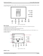
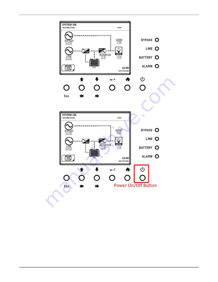
Step 5:

 Before UPS enters shutdown mode, please press “Power On/Off” button for 2

seconds immediately as shown in the diagram below


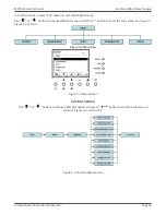
Step 6: 

UPS will enter Battery Mode as shown in the diagram below.

Summary of Contents for M90S Series

Page 1: ...M90S Online Split Phase UPS 6kVA 12kVA 18kVA 24kVA Models User Installation Manual www xpcc com 2019 Xtreme Power Conversion Corporation All rights reserved Rev 1 14 19 ...

Page 2: ...is Installation 18 2 11 Power Module Battery Pack Installation 18 3 Control Panel and Power Module LCD Descriptions 19 3 1 Control Panel 19 3 2 Power Module 21 3 3 UPS System Functional Description 23 4 Operation 27 4 1 AC Startup 27 4 2 Cold Start Startup Start up with no AC Power Pressed 29 4 3 Turn Off Operation 31 4 4 Battery Mode Turn Off Operation 34 4 5 Maintenance Bypass Switch Operation 3...

Page 3: ...Port 83 5 10 Battery Dry Contact 83 5 11 EPO Port 84 5 12 External Maintenance Bypass Signal Port EMBS 84 5 13 Other Communication Interfaces 85 6 Service 85 6 1 UPS Module Replacement 85 7 Troubleshooting 86 7 1 UPS Fault Code Descriptions 86 7 2 Control Panel Audible Alarms 89 8 Specifications 90 9 Obtaining Service 92 10 Xtreme Power Conversion Limited Warranty 93 11 Xtreme Power Conversion Loa...

Page 4: ...s including the protective earth Risk of Voltage Backfeed The isolation device must be able to carry the UPS input current 1 2 EMC WARNING This is a product for commercial and industrial application in the second environment installation restrictions or additional measures may be needed to prevent disturbances 1 3 Installation Information WARNING Installation must be performed by qualified personn...

Page 5: ...ectronic equipment WEEE in the trash For proper disposal contact your local recycling reuse or hazardous waste center 2 Installation 2 1 Initial Inspection 1 Visually examine if there is any damage inside and outside of packages in the process of the transportation If any damage report it to the carrier immediately 2 Verify the product label and confirm the consistency of the equipment 3 If the eq...

Page 6: ...s we suggest that you shall Equip with CO2 or dry powder fire extinguishers near the installation area Install the UPS in an area where the walls floors and ceilings were constructed by fireproof materials 9 Do not allow unauthorized personnel to enter the installation area Assign specific personnel to keep the UPS key 2 3 Unpacking 1 Use a forklift to move the product to installed area Please mak...

Page 7: ...s Manual Page 7 Uninterruptible Power Supply 1 2 3 3 Remove 2 fixing cabinet plates and loosen leveling feet by rotating them counterclockwise Then move the cabinet from the pallet 4 To fix the cabinet in position simply rotate leveling feet clockwise ...

Page 8: ...e suggest that at least three people move the UPS to the installation area One person holds a lateral side of the UPS with hands another holds the other lateral side of the UPS with hands and the other person pushes the UPS either from the front side or from the back side to the installation area to avoid tipping the UPS 3 The casters are designed to move on level ground Do not move the UPS on an ...

Page 9: ...xterior In the front of the UPS there are control interface LCD Panel 4 and 6 slot chassis Power Module slots and Battery Module slots A wiring terminal blocks circuit breakers communication slots 4 and 6 slot chassis communication ports are located at the back of cabinet The side panels are locked by screws The casters at the bottom of the UPS cabinet can be used to move the UPS for short distanc...

Page 10: ...Xtreme Power Conversion Corporation M90S 4S User s Manual Page 10 Uninterruptible Power Supply 2 Slot M90S 4 Slot M90S ...

Page 11: ...Emergency power off port 13 AC input breaker 14 AC output breaker 15 AC terminal 16 Output receptacles optional 17 External battery terminal 18 Maintenance bypass switch 19 DC Disconnect Switch 1 Control panel 2 Power module 3 LCD display on Power module 4 Battery module 5 Leveling foot 6 Caster 7 Controller module 8 Dry contact 9 RS 232 port ...

Page 12: ...nual Page 12 Uninterruptible Power Supply Controller Module 2 6 1 Mechanical Data Dimensions UPS cabinet Width Depth Height 2 Slot 17 36 30 59 10 51 4 Slot 17 44 33 74 33 07 6 Slot 17 44 33 74 45 43 7 Slot Battery 17 44 32 79 45 43 6U Rack 2 Slot Chassis ...

Page 13: ...Xtreme Power Conversion Corporation M90S 4S User s Manual Page 13 Uninterruptible Power Supply 4 Slot Chassis 6 Slot Chassis ...

Page 14: ...t open view After removing panel covers you will see the empty module slots and control panel Rear open view You will see the breakers terminal blocks receptacle panels and communication ports installed on the cabinet Front View Rear View 1 Control panel 2 Power battery module slots 3 Communication port 4 AC terminals 5 DC terminals 6 AC breakers ...

Page 15: ...minal block for the UPS input output wiring please check below chart and table Terminal Block Descriptions Item Function Description AC Terminal Output Block O P L1 O P L2 O P N Connects the criti cal loads Includes L1 L2 and Neutral terminals AC Input Block R T N Connects main AC source Includes L1 L2 and Neutral terminals For UPS Grounding PE For UPS grounding Includes one grounding terminal PE ...

Page 16: ...utput Model 6kVA 12kVA 18kVA 24kVA Current A 28 9 57 7 86 6 115 4 Recommended OCPD 40 75 110 150 Power cable AWG mm2 8 4 6 10 4 21 2 35 Torque force lb in 20 20 20 20 2 8 2 DC input maximum current and power cable configuration Model 6kVA 12kVA 18kVA 24kVA Current A 41 6 83 2 124 8 166 3 Power cable AWG mm2 6 10 4 21 2 35 1 0 50 Torque force lb in 20 20 20 20 Warning 1 One standard battery module ...

Page 17: ...Chassis Wiring 2 9 2 AC source connection Connect AC input to the AC power source Please refer to Installation Drawing for UPS wiring The polarity of two phase L1 phase and L2 phase are not critical The wrong polarity will not cause an alarm for UPS system when the UPS is powered The Neutral wire must be connected properly A warning message will be indicated if the Neutral wire is not con nected p...

Page 18: ...re two slot chassis with included brackets and screws Step 3 Install power module into top slot of 2 slot chassis Step 4 Install battery module into bottom slot of 2 slot chassis Step 5 Connect input and output electrical wiring to terminal block on rear of 2 slot chassis Refer to section 2 10 2 11 Power Module Battery Pack Installation 2 11 1 Insert the power module Warning The power modules inst...

Page 19: ...t least one power module MUST stay in the UPS cabinet in case the UPS system is operating in Maintenance Bypass Mode 1 1 Use a screwdriver to remove the four screws from fixing holes 2 Two people pull out together and remove the UPS module from its slot 2 11 3 Battery Module Installation Removal Please follow power module installation removal steps to install and remove battery packs NOTE Battery ...

Page 20: ...r mode Battery mode Fault mode Battery Test mode ECO mode Note means LED is lighting and means LED is faded 3 1 2 Function Keys Control Key Description Esc When it is the Main screen you can enter menu by pressing ESC key Return to previous screen when screen is not in Main screen Return to previous value in the same row so you can change it For example when changing 4 digit password press Esc to ...

Page 21: ...nd No 3 2 Power module Each power module is shipped with its own package It has to be installed during the whole sys tem installation The capacity of each power module is 6kVA 6kW It includes a power fac tor correction rectifier a battery charger an inverter a static bypass circuit and control circuit No Item Description 1 Fan The Power Module uses forced convection cooling by these fans Cooling a...

Page 22: ...on to turn on the UPS Or press it to confirm the selection in the menu OFF ESC Press this button to turn off the UPS Or press it to return to the last menu UP Press this button to select the previous item in the menu Or press this button to jump to previous page in the screen Or press this button to increase the number in the setting DOWN Press this button to select the next item in the menu Or pr...

Page 23: ...can be based on the initial needs Once the power requirement increases you can easily install more power modules without interrupting the opera tion of the system UPS module 3 3 1 Operation Mode This modular UPS is a two phase three wire on line double conversion and reverse transfer UPS that permits operation in the following modes Standby Mode Line Mode Battery Mode Bypass Mode ECO Mode Shutdown...

Page 24: ...er derives power from the utility power and supplies DC power to the inverter and the charger charges the battery The inverter filters the DC power and converts it into pure and stable AC power to the load Line Mode Diagram 3 3 4 Battery Mode The UPS automatically transfers to Battery mode if the utility power fails There is no interruption in power to the ...

Page 25: ... the UPS is in Bypass mode before UPS is turned on if BYPASS enable set ting is Enabled and charger function will be active when battery is present After UPS has been turned on if the UPS encounters abnormal situations over temperature overload etc the static transfer switch will perform as a transference of the load from the inverter to the bypass source with no interruption If the transference i...

Page 26: ...fer time the rectifier and inverter are working when the UPS is in ECO mode ECO Mode Diagram 3 3 7 Shutdown Mode When the UPS is in the off state and the utility power source is absent the UPS will enter shutdown mode Or when the UPS has discharged the battery to the cut off level the UPS will enter shutdown mode as well When the UPS enters this mode it is going to shut off the control power of UP...

Page 27: ... from a fully powered down condition The operating procedures are as follows Step 1 Refer to the Installation Section to connect the power cables and install the Power Modules and the bat tery required for the UPS system Step 2 Switch ON the battery breaker on the External Battery Pack if installed Step 3 Switch ON the external power switch to power the UPS Step 4 Switch ON the input breaker Q1 Th...

Page 28: ... is no warning or fault event happening If there is please refer to Chapter 6 Troubleshoot ing to solve it Step 6 Press Power ON OFF button for two seconds to enter Line Mode as shown below After turned on UPS will do self test and start Inverter up UPS will be transferred to Line mode when all power modules are ready ...

Page 29: ... Power pressed Step 1 Insert battery pack to 19U mini rack system Step 2 Press the Battery Start button on each power module to start up the control power of all power modules as shown below Step 3 Press the Battery Start button on communication module to start up the power as shown below Step 4 After pressing the Battery Start button UPS will enter Standby mode Refer to the diagram below for LCD ...

Page 30: ... User s Manual Page 30 Uninterruptible Power Supply Step 5 Before UPS enters shutdown mode please press Power On Off button for 2 seconds immediately as shown in the diagram below Step 6 UPS will enter Battery Mode as shown in the diagram below ...

Page 31: ... to Maintenance Bypass and UPS protection as below 4 3 Turn off Operation 4 3 1 Bypass Mode Standby Mode Turn Off Operation The UPS operates in the Standby Mode or Bypass Mode depending on the Bypass Mode Setting The LCD dia grams are shown below Bypass Mode Setting is Disabled Bypass Mode Setting is Enabled Step 1 Switch OFF the AC input breaker The LCD diagrams are shown below Wait until the LCD...

Page 32: ...reme Power Conversion Corporation M90S 4S User s Manual Page 32 Uninterruptible Power Supply Bypass Mode Setting is Disabled Bypass Mode Setting is Enabled UPS enters Shutdown Mode UPS enters Standby Mode ...

Page 33: ...al to show Un Connection screen when UPS modules have shut off their control power UPS enters Shutdown Mode It is normal to show Un Connection screen when UPS modules have shut off their control power 4 3 2 Line Mode Turn Off Operation The LCD diagrams are shown below when the UPS operates in the Line Mode ...

Page 34: ...e UPS Or use the Menu Control System Turn Off to turn off the UPS After turning off the UPS will tranfer to Standby Mode or Bypass Mode depending on the Bypass Mode Setting Next follow the Bypass Mode Standby Mode Turn Off Operation procedure 4 4 Battery Mode Turn Off Operation The LCD diagram is shown below when the UPS operates in the Battery Mode ...

Page 35: ...n Off button for 2 seconds to turn off the UPS Or use the Menu Control System Turn Off to turn off the UPS After turning off the UPS will tranfer to Standby Mode Next follow the Bypass Mode Standby Mode Turn Off Operation procedure 5 Control Panel and Display Description 5 1 System 5 7 LCD Screen Description ...

Page 36: ...ull the outside edges of the LCD Display panel housing out and down to gain access to the maintenance bypass switch Step 2 Remove the MBS small metal cover with 2 screws Step 3 Make sure the UPS is operating in static Bypass mode Step 4 Switch ON the Maintenance Bypass Breaker as shown below Now it is possible to perform maintenance on the UPS without affecting the load equipment ...

Page 37: ...n choose SYSTEM to ensure that the Static Bypass mode is en abled If the Static Bypass mode is disabled you have to enable it Then exit the SETUP menu and ensure that the UPS operates in static bypass mode Step 3 Switch OFF the Maintenance Bypass Breaker as shown below Step 4 re insert the 2 screws on the MBS breaker cover For the four and six slot chassis re install the LCD display panel housing ...

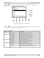
Page 38: ...1 Initial screen Main Screen After initialization the main screen will display as Figure 5 2 Main screen is divided into five parts 1 UPS Mode Current operation mode 2 UPS Flow Chart Current flow chart and measurement data 3 Menu Press Esc button to enter Menu screen 4 UPS model name with power rating If the power rating followed with R it means the UPS system is in re dundant configuration 5 Date...

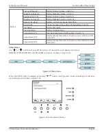
Page 39: ...nter the MENU screen Use or buttons to choose different menus and Press button to enter the sub screen as shown in Figure 5 3 and 5 4 Figure 5 3 Menu tree Figure 5 4 Menu screen Control Screen Use or buttons to choose CONTROL option and press button to enter the submenu as shown in Figure 5 5 5 6 and 5 7 Figure 5 5 Control submenu tree ...

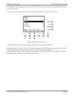
Page 40: ...y Figure 5 6 Control screen page 1 Figure 5 7 Control screen page 2 When the control option is selected by pressing button the confirmation screen will pop up Use or button to choose V YES or X NO Choose V and press button to confirm command or choose X to cancel command as shown in Figure 5 8 ...

Page 41: ...e 41 Uninterruptible Power Supply Figure 5 8 Confirmation screen Measurement Screen Use or button to choose MEASUREMENT option and press button to go into the submenu as shown in Figure 5 9 and 5 10 Figure 5 9 Measurement menu Figure 5 10 Measurement Menu Screen ...

Page 42: ...e 4 1 Measurement data Menu Item Explanation Input L N Voltage V Input phase voltage L1 L2 Units 0 1V Frequency Hz Input Frequency L1 L2 Units 0 1Hz Outpu L N Voltage V Output phase voltage L1 L2 Units 0 1V L N Current A Output phase current L1 L2 Units 0 1A Frequency Hz Output Frequency L1 L2 Units 0 1Hz Power Factor Output Power Factor L1 L2 Bypass L N Voltage V Bypass phase voltage L1 L2 Units ...

Page 43: ...ttery test result Charging Status Battery charging status Temperature1 C Internal temperature of UPS module Units 0 1 C Temperature2 C Battery cabinet temperature of extra communication card T1 Units 0 1 C Temperature3 C Battery cabinet temperature of extra communication card T2 Units 0 1 C Setup Screen Use or button to choose SETUP options It s required to enter password to access GENERAL SYSTEM ...

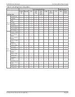
Page 44: ...s shown in Figure 5 14 Figure 5 14 SETUP Submenu Screen There are two levels of password protection user password and maintainer password The default password for user is 0000 It could be changed by user The default password for service is 0729 This password is controlled by service personnel and can be chanced as appropriate Entering different levels of password gives access to different settings...

Page 45: ... Y Y Y Y Y Y Y Change Y Y Y Y Y Y Y Y Y Y Password Y Y Y Y Y Y Y Y Y Y Audible Alarm Y Y Y Y Y Y Y Y Y Y Factory Reset Y Y Y EPO Function Y Y Sys tem Output Voltage Y Y Y ECO Voltage Range Y Y Y Y Y ECO Frequency Range Y Y Y Y Y Bypass Voltage Range Y Y Y Bypass Fre quency Range Y Y Y ECO Mode Y Y Y Y Y Bypass Mode Y Y Y Converter Mode Y Y Y Battery Mode Delay Time Y Y Y Y Y Y Y Cold Start Y Y Y Y...

Page 46: ... Y Y Y Battery Test Interval Y Y Y Y Y Y Y Y Y Battery Test Type Y Y Y Y Y Y Y Y Battery Age Alert Y Y Y Y Y Y Y Y Y Pre Alarm Y Y Y Y Y Y Y Y Y Y means that this setting item can be set in this operation mode 5 2 Setup General Screen Use or buttons to choose between different sub menus and press button to go into the GEN ERAL setting screen as shown in Figure 5 15 and 5 16 General setting can be ...

Page 47: ...ral Screen page 2 Use or buttons to choose the setting options for setting requirement then press button The confirmation screen will pop up Use or button to choose V YES or X NO Choose V and press button to confirm setting or choose X to cancel the setting as shown in Figure 5 17 Figure 5 17 SETUP Confirmation screen ...

Page 48: ...yy mm dd 2017 1 1 Default MUST be set after UPS installation Battery Installed Date Set battery installed date yyyy mm dd 2017 1 1 Default MUST be set after UPS installation Battery Last Maintain Date Set battery latest maintenance date yyyy mm dd 2017 1 1 Default MUST be set after UPS installation Change Password Change Password Audible Alarm Audible Mute It is to mute the buzzer when UPS in any ...

Page 49: ...ninterruptible Power Supply Setup System Screen Use or button to choose between different sub menus and press button to go into the SYSTEM setting screen as shown in Figure 5 18 5 19 and 5 20 Figure 5 18 Setup System Screen page 1 Figure 5 19 Setup System Screen page 2 ...

Page 50: ...ly Figure 5 20 Setup System Screen page 3 System setting can be set only when UPS is operating in certain mode Please check Table 5 2 for the available operation modes If it s not able to set up in specific mode the warning screen will appear as shown in Figure 5 21 Figure 5 21 Warning screen ...

Page 51: ...etting Voltage 6V Output Setting Voltage 12V Output Setting Voltage 6V Default Lower Range Output Setting Voltage 6V Output Setting Voltage 12V Output Setting Voltage 6V Default ECO Frequency Range Set bypass Frequency range Upper Lower limit 2Hz Default 3Hz 4Hz Bypass Setting Bypass Voltage Range Set bypass voltage range Upper Range Output Setting Voltage 6V 155V 140V Default Lower Range Output S...

Page 52: ... Default Not 0 Enable When this feature is enabled UPS will shut off output after UPS oper ates in Battery mode for certain seconds Cold Start Set system shutdown time 0 2 99min 0 2 min Default This delay time will start counting when the CONTROL Shutdown Restore com mand is executed System Shutdown Time Set system restore time 0 9999min 1 min Default This delay time will start counting after shut...

Page 53: ...nus Press button to go into the BATTERY setting screen as shown in Figure 5 22 and 5 23 Figure 5 22 Setup Battery Screen page 1 Figure 5 23 Setup Battery Screen page 2 Battery setting can be set only when UPS is operating in standby mode If it s not in standby mode the warning screen will appear as shown in Figure 5 24 See Setup Battery setting list in Table 4 6 ...

Page 54: ...26 40 65 100Ah MUST be set after UPS installation or Battery capacity is changed Battery Groups Set battery Groups 1 default Maximum Charging Current Set battery maximum charging current 1 10 4A Default MUST be set after UPS installation or Battery capacity is changed Battery Low Shutdown SETTING Battery Low Voltage Set battery low voltage 10 5 11 5V x battery Number 11 2V x Battery Number Default...

Page 55: ...g Time 0 1M 0 9M Long Time 1M 99M Till Battery Low Battery Age Alert Battery Age Alert Months Set battery age for replacement Disable 12 60Months Disable Default If this feature is enabled and the battery has been installed over this period there is a warn ing Battery Age Alert to indicate it 5 2 3 Pre Alarm Screen Use UP and DOWN buttons to switch different sub menus Press ENTER button to go into...

Page 56: ... Line Frequency Range Set line frequency range Upper Lower limit 1Hz 2Hz 3Hz 4Hz Default Load Set UPS Overload percentage 40 100 100 Default Set UPS load unbalance percentage 20 100 100 Default 5 2 4 Information Screen In INFORMATION menu you can check the serial number firmware versions system configuration and settings of the UPS There are submenus under the INFORMATION including Identification ...

Page 57: ...odel Name Serial No and Firmware Version will be displayed Use UP and DOWN buttons to switch between different pages Identification screen page 1 Identification screen page 2 5 2 4 2 INFORMATION System Screen When System submenu is selected the system power nominal voltage nominal frequency etc information will be displayed Use UP and DOWN buttons to switch between different pages ...

Page 58: ...r Supply INFORMATION System screen page 1 INFORMATION System screen page 2 5 2 4 3 INFORMATION Battery Screen When Battery submenu is selected the Battery nominal voltage capacity charging current etc information will be displayed Use UP and DOWN buttons to switch between different pages ...

Page 59: ...0S 4S User s Manual Page 59 Uninterruptible Power Supply INFORMATION Battery screen page 1 INFORMATION Battery screen page 2 5 2 5 Events Screen In EVENT menu you can check the current events history events and reset all events Events menu ...

Page 60: ...ing warning text in the Main Screen Alarm warning screen 5 2 5 1 Current Events When any event occurs it will display Module ID and alarm code in Current Events screen It can save up to 50 events in current list Only 4 events can be listed in one page Therefore if it exceeds more than four you have to press UP or DOWN button to read other events ...

Page 61: ... occurs it will display alarm code alarm time Module ID and data 1 2 In order to record more historical information about the UPS system the important setting changed UPS operation mode changes and control action executes will be saved in History Events History Events screen 5 2 5 3 Reset All Events The Maintainer password is required to enter Reset All Events screen as shown in Figure 4 42 Then u...

Page 62: ...em No Description 1 Setup Model Name 2 Setup Language 3 Setup Adjust Time 4 Setup System Installed Date 5 Setup System Last Maintain Date 6 Setup Battery Installed Date 7 Setup Battery Last Maintain Date 8 Setup Change Password 9 Setup Audible Alarm 10 Setup Factory Reset 11 Setup EPO Function 12 Setup Output Voltage 13 Setup ECO Voltage Range 14 Setup ECO Frequency Range 15 Setup Bypass Voltage R...

Page 63: ...Y Age Alert 39 Setup Line Voltage Range 40 Setup Line Frequency Range 41 Setup Load 42 The table below provides the complete list of UPS alarm messages Table 5 9 UPS operation mode Item No Description Item No Description 1 UPS Mode Power On Mode 2 UPS Mode Standby Mode 3 UPS Mode Bypass Mode 4 UPS Mode Line Mode 5 UPS Mode Battery Mode 6 UPS Mode Battery Test Mode 7 UPS Mode Fault Mode 8 UPS Mode ...

Page 64: ...terface Home Page 1 UPS Mode Current operation mode 2 It will display the UPS running status mode and parallel information as below table Short Description Description N New adding module into parallel system M Master S n Slave n means the number of slave module 3 Input and output information 4 Battery capacity load level and backup time warning or fault codes When alarms happen the warning or fau...

Page 65: ...t operated for 2 minutes the display page will return back to home page Press the UP or DOWN button to enter the operation menu Refer to 4 2 3 When it displays home page in LCD if UPS is in bypass or standby you could press the ON ENTER button to turn on the UPS to line converter ECO battery mode according to the setting and input status When UPS is turned on you could press the OFF ESC button to ...

Page 66: ...2 Press UP or DOWN button to select item 3 Press ON ENTER button to confirm the selection 4 Press OFF ESC button to return back to main scree Home page Control In Control screen it s real time command for UPS Turn On will be displayed if UPS is not turned on Turn Off will be displayed if UPS is turned on Bat Test will be displayed if UPS is not in Battery Test Mode Cancel Test will be displayed if...

Page 67: ...transfer to line mode converter mode ECO mode or battery mode according to the setting and input status NOTE You may simply turn on UPS by pressing ON ENTER button in main scree Home page It s not necessary to enter control menu to turn on the UPS b On line mode converter mode ECO mode or battery mode it will display Turn Off in control menu If it is selected and confirmed the UPS will transfer to...

Page 68: ... will change back to UPS current mode There are four battery test types to select Refer to Table 4 11 Table 4 11 Battery Test Type Setting Item Sub Item Explanation Bat Test Type Short Time 10 second test time Long Time When testing time is longer than 1 minute please select Long Time and the duration is able to set up 1 99min 10 min Default Till to Bat Low Test until the battery is low voltage b ...

Page 69: ...ay SR On in control menu If it is selected and confirmed the screen will return back to home page Shutdown and restore time can be selected as in Table 4 12 When Shutdown Time countdown ends the UPS will turn off Then the Restore Time will start to count When countdown ends the UPS will be turned on and back to current mode Bypass Mode M IP1 230 0V 50 0Hz IP2 230 0V 50 0Hz IP3 230 0V 50 0Hz OP1 23...

Page 70: ...is selected and confirmed the screen will return back to home page and system will back to current mode If SR On is selected and confirmed When UPS in Line Battery Battery Test Converter ECO mode it will display SR Off in control menu If it is selected and confirmed the screen will return back to home page and system will cancel this function 5 Charger Off Charger On a Charger Off will be displaye...

Page 71: ...nd charger will charge the battery 5 4 2 Measurement Measurement displays the measurement value of the parameters such as voltage current frequency power capacity time etc Every UPS could display the measured value of the whole system Press up or down button to explore the pages Local means the current UPS module System means the whole M90S system Master and Slave n means the other UPS module in t...

Page 72: ...s If the setting is not available in current mode the LCD will show prompt message with Item can t be set in this mode Press any button or just wait for several seconds until this message fades Measurement Input Output Bypass Load Bat Input Volt1 230 0V Volt2 230 0V Volt3 230 0V Freq 50 0Hz Phase 120 Output Volt1 230 0V Volt2 230 0V Volt3 230 0V Inv1 230 0V Inv2 230 0V Inv3 230 0V Freq 50 0Hz Curr...

Page 73: ...e Then the UPS will go to bypass mode but without output if it is turned off in AC mode The default setting is Enable NOTE The following items are only available in bypass mode 2 HighLoss V Set the acceptable high voltage for bypass For 3 3 10K 3 1 10K and 1 1 10K models Setting range is from Rated Output Volt 11V to 276V and the default value is 264V For 2 2 6K and 3 3 10K LV models Setting range...

Page 74: ...efault setting is Rated Output Volt 11V For 2 2 6K and 3 3 10K LV models The setting range is from Rated Output Volt 6V to Rated Output Volt 12V and the default setting is Rated Output Volt 6V 3 LowLoss V Low voltage point in ECO mode For 3 3 10K 3 1 10K and 1 1 10K models The setting range is from Rated Output Volt 24V to Rated Output Volt 11V and the default setting is Rated Output Volt 11V For ...

Page 75: ... rated output voltage with 120Vac 127 Presenting the rated output voltage with 127Vac The default value is 120Vac 2 Freq 50Hz The output frequency is setting for 50Hz 60Hz The output frequency is setting for 60Hz NOTE CVCF should be enabled to modify this item If CVCF is disabled output frequency will be decided according to the latest normal utility frequency If it is within 46Hz and 54Hz the out...

Page 76: ... mode English All interface will show in English 4 Bat Mute available or effective on all modes Enable It is to mute the buzzer when UPS in Battery mode Disable It is to enable the buzzer in Battery mode The default setting is Disable 5 Fault Mute available or effective on all mode Enable It is to mute the buzzer when UPS in Fault mode Disable It is to enable the buzzer in Fault mode The default s...

Page 77: ...er test the LCD screen will return to main scree home page and show bat tery voltages on BAT and BAT 5 Low Volt Set battery low warning voltage The setting range is from 10 5 11 5V per piece The default value is 11 2V 6 Under Volt Set battery low cut off voltage The setting range is from 9 6 10 7V per piece The default value is 9 6V 7 Periodic Test Enable UPS will test the battery periodically Dis...

Page 78: ...ion and settings of the UPS There are submenus under the Information including Identification System and Battery as shown below Information displays all parameter setting value and status 1 Identification shows the UPS Module name serial no UPS display version controller module version CPU version and system LCD version 2 System shows the UPS configuration 3 Battery shows the battery configuration...

Page 79: ...display alarm code in Current Events page If events exceed more than one page press or button to read other events 2 History Events The detailed event information is saved in history events It can save up to 160 pages in history events When a warning occurs it will display alarm code alarm time and UPS mode When a fault event occurs it will display fault code alarm time date and UPS operation mode...

Page 80: ...eset action The default password is 0729 5 5 Controller Module Front View Back View EMBS port external maintenance bypass signal port 5 6 Battery Start Button The controller module can be turned on without connecting to utility by pressing Battery Start Button 5 6 1 Status LED The green LED represents operation status of controller module Color Status Definition Green Flashing Communications On 0 ...

Page 81: ...the Dry Contact Config tool Please refer to next section for the detailed installation and configuration 5 8 Configuration Step 1 Please access the www power software download com and select Communication Setting Tool icon Please download and install this tool in your computer After this tool is installed successfully it will leave a short icon on the desktop Step 2 Start this tool in your compute...

Page 82: ...ible Power Supply Step 3 Click Read Setting button to check the current setting of the output dry contact port Step 4 Check all settings There are 18 options to select for contact and listed in Table 5 1 Once output dry contact settings are selected click Setting Confirm button ...

Page 83: ...tion fail ure Communication error between UPS modules 9 Output overload warning shutdown Connected load is over rated output of the UPS 10 UPS module fault shutdown The module fails and the UPS shuts down 11 UPS module warning The module has errors but the UPS can still function normally 12 EPO Active Urgently power off the UPS 13 Maintain Bypass The UPS transfers to Maintain bypass mode 14 Module...

Page 84: ...ut Dry Contact Port There are two sets of input dry contact to receive external signals for UPS to take response 5 10 Battery Dry Contacts Option This port is to detect the temperature of external battery packs It s necessary to install sensor kit optional accessory when using these battery dry contacts ...

Page 85: ...hen Pin1 Pin2 is short circuited If EPO logic setting is Normal Closed N C EPO is triggered when pin1 and pin2 is open Otherwise EPO logic setting is Normal Opened N O EPO is triggered when pin1 and pin2 is connected 5 12 External Maintenance Bypass Signal Port EMBS On the back panel of controller module there is an external maintenance bypass signal port The jumper on the EMBS port is electricall...

Page 86: ... Battery SCR is short circuited Contact service personnel Fault 11 Inv Start Fail Inverter voltage cannot reach desired voltage within specified time Turn off UPS and then restart it If it fails again contact service personnel Fault 12 Inv Volt High Inverter voltage is too high Contact service personnel Fault 13 Inv Volt Low Inverter voltage is too low Contact service personnel Fault 14 Inv Short ...

Page 87: ... between UPS modules is incompatible Contact service personnel Fault 41 DSP Comm Fail The internal communication in UPS module is interrupted Contact service personnel Fault 42 Over load Heavy overload causes UPS fault Reduce some load Fault 43 Charger Fail Battery polarity is connected reverse ly or charger voltage is abnormal Fault 44 Model Fault UPS model is not able to identify Contact service...

Page 88: ...1 BypassIpNLoss Neutral loss Check if the Neutral connection is well and contact service personnel Warning 12 BpsPhaseError Bypass phase error Check if the Bypass phase sequence is correct and contact service person nel Warning 13 BpsVoltError Bypass voltage error Check the wiring or contact service personnel Warning 14 BpsPhaseFail As stated Contact service personnel Warning 15 OverLoad In line m...

Page 89: ...tated Check if redundancy setting is correct or not Then contact service person nel Warning Battery Age Alert Battery life is expired Check if the battery has been used over its service age Or contact ser vice personnel Warning Dry Contact Input Alarm 1 As stated Remove the node Warning Dry Contact Input Alarm 2 As stated Remove the node Warning COMM Module SPS 1 Fault As stated Contact service pe...

Page 90: ... load level Battery Life is reduced above 30 C UPS Capacity derates above 30 C and 5 200 ft above sea level MODEL NUMBER M90S 4S6K M90S 4S12K CAPACITY Power Rating 6kVA 6kW 12kVA 12kW INPUT Voltage frequency nomi nal 120 208V or 120 240V 50 60Hz auto sensing 2PH N G Voltage frequency range 121 253VAC L L 40 70Hz OUTPUT Voltage Frequency 120 208V or 120 240V 50 60Hz 0 1Hz 2PH N Efficiency THD full ...

Page 91: ...ght 17 4 W x 33 7 D x 45 5 H UPS BAT ENC UPS 180lbs Battery 162lbs Maximum Capacity 24kVA Enclosure Capacity 6 Slots including 4 universal slots 2 battery only slots Optional Battery Enclo sure 7 Slots for additional battery modules Output Connections Terminal blocks and or up to 4 receptacle panels ENVIRONMENT Temperature 0 40 C 32 104 F Altitude 5 200 ft above sea level Audible noise 58dBA at 1m...

Page 92: ...ll ask you for the above information and if possible help solve your problem over the phone In the event that the unit requires factory service the technician will issue you a Return Mate rial Authorization number RMA If you are returning the UPS to Xtreme Power for service please follow these procedures 1 Pack the UPS in its original packaging If the original packaging is no longer available ask ...

Page 93: ...ration approved third party b the equipment is damaged by the customer is improperly used or stored is subjected to an adverse operating environment or is operated outside the limits of its electrical specifi cations or c the equipment has been used or stored in a manner contrary to the equipment s operating manual intended use or other written instructions Any technical advice furnished by XPC Co...

Page 94: ... certain terms and conditions provided below This policy applies only to the original purchaser of the Product If the Product is transferred or sold to another person or entity this policy is void Load Protection Policy Dollar and Period Limits For purchasers that meet the qualifications and conditions set forth in this policy XPC will provide reimbursement cost of repair or fair market value as d...

Page 95: ...sed by the use of the Product for purposes other than those for which it was designed 5 Damage caused by accidents or natural disasters including but not limited to fire flood and wind 6 Damage caused by abuse misuse alteration modification or negligence 7 Any labor costs or travel room and board expenses associated with the repair and or restoration of lost or damaged hardware software or data EX...

Page 96: ...rchaser to transfer title and deliver the Connected Equipment to XPC if it chooses to reimburse the Purchaser for the fair market value of the Connected Equipment XPCs maximum liability shall be reduced to reflect all such other payments or sources of recovery whether applied for or not 4 If XPC issues payment to the Purchaser to have the Connected Equipment repaired the repair must be per formed ...

Reviews: