background image

Xtreme Power Conversion Corporation

TX90 User’s Manual

Page 3

Uninterruptible Power Supply

Important Safety Warning

Please comply with all warnings and operating instructions in this manual strictly. Save this manual properly and 

read carefully the following instructions before installing the unit. Do not operate this unit before reading through 

all safety information and operating instructions carefully.

Transportation

•  Please transport the UPS system only in the original package to protect against shock and impact.

Preparation

•  Condensation may occur if the UPS system is moved directly from cold to warm environment. The UPS 

system must be absolutely dry before being installed. Please allow at least two hours for the UPS system 

to acclimate the environment.

o  Do not install the UPS system near water or in moist environments.

•  Do not install the UPS system where it would be exposed to direct sunlight or near heater.

•  Do not block ventilation holes in the UPS housing.

Installation

•  Do not connect appliances or devices which would overload the UPS system to the UPS output sockets.

o  Place cables in such a way that no one can step on or trip over them.

o  The UPS can be operated by any individuals with no previous experience.

•  Connect the UPS system only to an earthed shockproof outlet which must be easily accessible and close 

to the UPS system.

•  Please use only VDE-tested, CE-marked mains cable (e.g. the mains cable of your computer) to connect the 

UPS system to the building wiring outlet (shockproof outlet).

•  Please use only VDE-tested, CE-marked power cables to connect the loads to the UPS system.

•  When installing the equipment, it should ensure that the sum of the leakage current of the UPS and the 

connected devices does not exceed 3.5mA.

Operation

•  Do not disconnect the mains cable on the UPS system or the building wiring outlet (shockproof socket 

outlet) during operations since this would cancel the protective earthing of the UPS system and of all con-

nected loads.

•  The UPS system features its own, internal current source (batteries). The UPS output sockets or output ter-

minals block may be electrically live even if the UPS system is not connected to the building wiring outlet.

o  In order to fully disconnect the UPS system, first press the OFF/Enter button to disconnect the 

mains.

o  Prevent no fluids or other foreign objects from inside of the UPS system.

Maintenance, Service, and Faults

•  The UPS system operates with hazardous voltages. Repairs may be carried out only by qualified mainte-

nance personnel. 

•  Caution - 

risk of electric shock. Even after the unit is disconnected from the mains (building wiring outlet), 

components inside the UPS system are still connected to the battery and electrically live and dangerous.

•  Before carrying out any kind of service and/or maintenance, disconnect the batteries and verify that no 

Summary of Contents for TX90-1000

Page 1: ...TX90 Isolated Online UPS 1000VA 2000VA 3000VA 5000VA Models User Installation Manual www xpcc com 2015 Xtreme Power Conversion Corporation All rights reserved Rev 4 06 15 ...

Page 2: ...Setup 6 Rear Panel View 6 Setup the UPS 8 Operations 10 ButtonOperation 10 LCDPanel 11 AudibleAlarm 12 LCD Display Wordings Index 12 UPS Setting 13 Operating Mode Description 17 Faults Reference Code 18 Warning Indicator 18 Troubleshooting 19 Storage And Maintenance Operation 21 Specifications 22 Obtaining Service 23 Xtreme Power Conversion Limited Warranty 24 Xtreme Power Conversion Load Protecti...

Page 3: ...accessible and close to the UPS system Please use only VDE tested CE marked mains cable e g the mains cable of your computer to connect the UPS system to the building wiring outlet shockproof outlet Please use only VDE tested CE marked power cables to connect the loads to the UPS system When installing the equipment it should ensure that the sum of the leakage current of the UPS and the connected ...

Page 4: ...inals and the ground Before touching please verify that no voltage is present Batteries may cause electric shock and have a high short circuit current Please take the precautionary measures specified below and any other measures necessary when working with batteries o Remove wristwatches rings and other metal objects o Use only tools with insulated grips and handles When changing batteries install...

Page 5: ...age 5 Uninterruptible Power Supply Installation And Setup Note Before installation please inspect the unit Be sure that nothing inside the package is damaged Please keep the original package in a safe place for future use Rear Panel View TX90 1000 TX90 2000 ...

Page 6: ...interruptible Power Supply TX90i 5000 1 Output receptacles 2 AC input 3 Input circuit breaker 4 External battery connection only available for L model 5 RS 232 communication port 6 Modem Phone line Network surge protection 7 Intelligent slot 8 Output circuit breaker ...

Page 7: ...communication cable one end to the RS 232 port and the other to the communication port of your PC With the monitoring software installed you can schedule UPS shutdown start up and monitor UPS status through PC 1kVA 2kVA 3kVA 5kVA models are equipped with intelligent slot perfect for SNMP RS 232 USB or Relay AS400 card When installing with these communication card in the UPS it will provide advance...

Page 8: ...oring software from the internet 1 Go to the website http www power software download com 2 Click ViewPower software icon and then choose your required OS to download the software 3 Follow the on screen instructions to install the software 4 When your computer restarts the monitoring software will appear as an orange plug icon located in the system tray near the clock Step 7 External battery conne...

Page 9: ...normal or transfer to Bypass mode if the Bypass enable setting by press ing this button Confirm selection key Press this button to confirm selection in UPS set ting mode Select Button Switch LCD message Press this button to change the LCD message for input voltage input frequency battery voltage output voltage and out put frequency It will return back to default display when pausing for 10 seconds...

Page 10: ...rs Indicates the warning and fault codes and the codes are listed in details in 3 5 section Mute operation Indicates that the UPS alarm is disabled Output Battery voltage information Indicates the output voltage frequency or battery voltage Vac output voltage Vdc battery voltage Hz frequency Load information Indicates the load level by 0 25 26 50 51 75 and 76 100 Indicates overload Indicates the l...

Page 11: ...rking Indicates the output is working Audible Alarm Battery Mode Sounding every 4 seconds Low Battery Sounding every second Overload Sounding twice every second Fault Continuously sounding Bypass Mode Sounding every 10 seconds LCD Display Wordings Index Abbreviation Display content Meaning ENA Enable DIS Disable ESC Escape HLS High loss LLS Low loss BAT Battery CF Converter TP Temperature CH Charg...

Page 12: ...s for each program 01 Output voltage setting Interface Setting For 208 220 230 240 VAC models you may choose the fol lowing output voltage Default 230Vac 120Vac 208 presents output voltage is 208Vac 220 presents output voltage is 220Vac 230 presents output voltage is 230Vac 240 presents output voltage is 240Vac For 110 115 120 127 VAC models you may choose the fol lowing output voltage 110 present...

Page 13: ... 176V to 190V half of the setting voltage in LV mains For Vout 110 115 120 127 VAC models the setting range is from 88V to 95V twice of the setting voltage in HV mains 03 ECO enable disable Interface Setting ENA ECO mode enable DefaultDIS DIS ECO mode disable 04 ECO voltage range setting Interface Setting Press the Down key or Up key to set the acceptable high volt age point and acceptable low vol...

Page 14: ...c to 220Vac For 110 150 120 127 VAC models HLS Bypass high voltage point setting the high voltage point from 120Vac to 132Vac LLS Bypass low voltage point setting the high voltage point from 88Vac to 115Vac Note When the bypass voltage range setting the ups can not return to bypass mode again 07 Bypass frequency range setting Interface Setting Press the Down key or Up key to set the acceptable hig...

Page 15: ...tion Interface Setting DISCHARGETIME SETTING NUMBER 60 SECOND Default 999 0 DISCHARGE AT LEAST 10 SECOND 999 DISABLE THIS FUNCTION 09 Battery AH setting Interface Setting Press the function key to set the Battery AH of UPS 0 999 if you change the battery AH of UPS please set the cor rect AH for the ups Unit AH ...

Page 16: ...ing mode When the input voltage is within voltage regulation range UPS will bypass voltage to output for energy saving Battery mode When the input voltage is beyond the acceptable range or power failure and alarm is sounding ev ery 4 second UPS will backup power from battery Bypass mode When input voltage is within acceptable range but UPS is overload UPS will enter bypass mode or bypass mode can ...

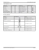
Page 17: ...oltage too high 27 Bus unbalance 04 x Battery voltage too low 28 Inverter soft start fail 11 x Over temperature 41 x Inverter voltage high 12 x Over load 43 Warning Indicator Warning Icon flashing Alarm Low Battery Sounding every second Overload Sounding twice every second Battery is not connected Sounding every second Over Charge Sounding every second Over temperature Sounding every second Charge...

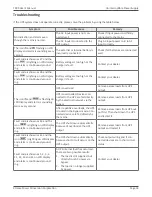
Page 18: ...shing on LCD display and alarm is sounding twice every second UPS is overload Remove excess loads from UPS output UPS is overloaded Devices con nected to the UPS are fed directly by the electrical network via the Bypass Remove excess loads from UPS output After repetitive overloads the UPS is locked in the Bypass mode Con nected devices are fed directly by the mains Remove excess loads from UPS ou...

Page 19: ...ible Power Supply Battery backup time is shorter than nominal value Batteries are not fully charged Charge the batteries for at least 5 hours and then check capacity If the problem still persists consult your dealer Batteries defect Contact your dealer to replace the battery ...

Page 20: ...replaced In this case please contact your dealer Be sure to deliver the spent battery to a recycling facility or ship it to your dealer in the replacement battery packing material Storage Before storing charge the UPS 5 hours Store the UPS covered and upright in a cool dry location During storage recharge the battery in accordance with the following table Storage Temperature Recharge Frequency Cha...

Page 21: ...Half load 11 min full load 5 min Recharge 5 hours to 90 capacity PHYSICAL UPS dimensions 5 7 x 16 6 x 13 1 in 7 5 x 16 8 x 17 6 in W x D x H 145 x 421 x 332 mm 190 x 426 x 448 mm UPS weight 58 5 lbs 26 5 kg 89 lbs 40 5 kg 136 lbs 61 7 kg 156 lbs 70 8 kg Input connection IEC C14 inlet Terminal block w IEC C20 Hardwired or input cord optional Receptacles TX90 4 5 15R 8 5 15 20R 6 5 15 20R HW N A Rec...

Page 22: ...ask you for the above information and if possible help solve your problem over the phone In the event that the unit requires factory service the technician will issue you a Return Mate rial Authorization number RMA If you are returning the UPS to Xtreme Power for service please follow these procedures 1 Pack the UPS in its original packaging If the original packaging is no longer available ask the...

Page 23: ...quipment is repaired or modified by anyone other than XPC Corporation or a XPC Corporation approved third party b the equipment is damaged by the customer is improperly used or stored is subjected to an adverse operating environment or is operated outside the limits of its electrical specifi cations or c the equipment has been used or stored in a manner contrary to the equipment s operating manual...

Page 24: ...PC Limited Warranty against certain losses caused by a Power Disturbance for properly connected electronic equipment referred to as the Connected Equipment subject to certain terms and conditions provided below This policy applies only to the original purchaser of the Product If the Product is transferred or sold to another person or entity this policy is void Load Protection Policy Dollar and Per...

Page 25: ...ad Protection Policy The following damage is not covered by this Policy 1 Restoration of lost data and reinstallation of software 2 Damage from a cause other than AC power line transients except for damage due to telephone line Local Area Network or CATV transients which is covered only if the Product offers such protection 3 DAMAGE CAUSED BY FAILURE TO PROVIDE A SUITABLE INSTALLATION ENVIRONMENT ...

Page 26: ...e payment to the Purchaser for either the cost of repair of the Connected Equipment or the Fair Market Value of the damaged Connected Equipment up to the dollar limits stated above XPC reserves the right to require the Purchaser to transfer title and deliver the Connected Equipment to XPC if it chooses to reimburse the Purchaser for the fair market value of the Connected Equipment XPCs maximum lia...

Reviews: