XPRT-6kVA, XPRT-10kVA USER’S MANUAL
UNINTERRUPTIBLE POWER SUPPLY (UPS)
Xtreme Power Conversion® (XPC) Corporation
Page 52
4.
For a quick start of the system, proceed to the Startup section of this manual.
5.
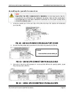
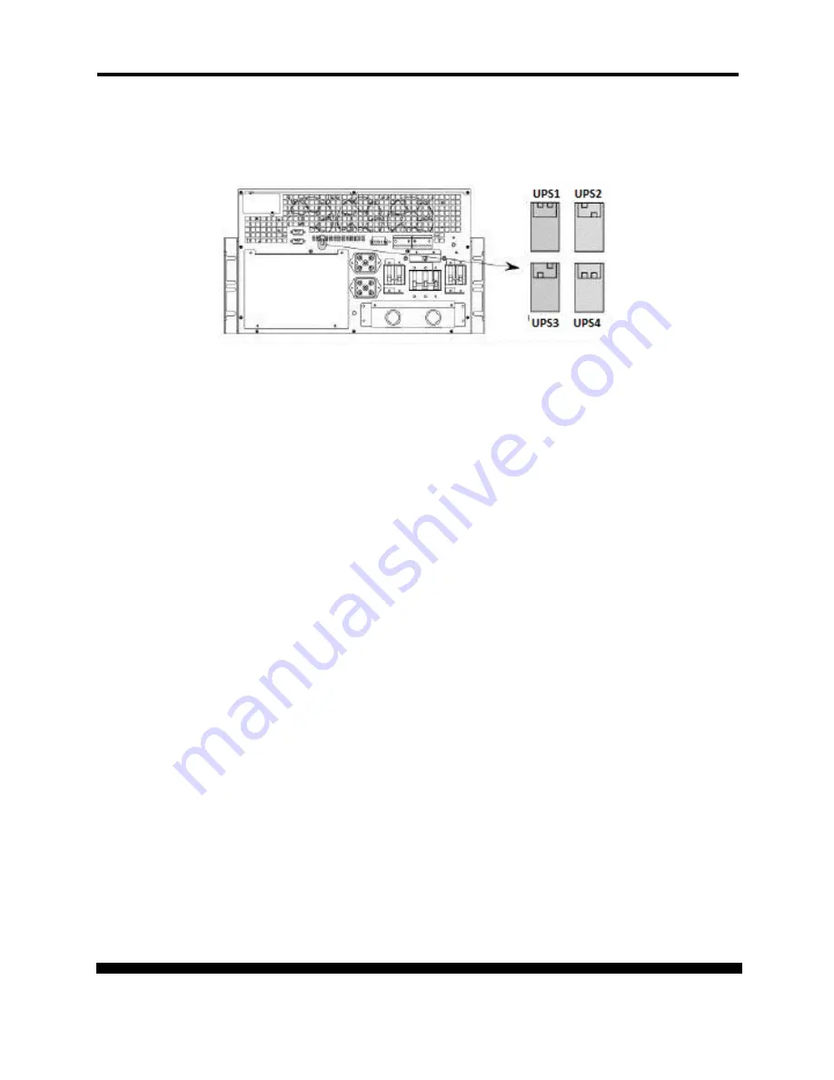
Each UPS needs a different configuration of the DIP switch as identification of unit in the parallel
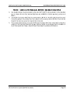
system (FIG 63).
FIG 63 –PARALLEL DIP SWITCH
Startup 10kVA UPS Parallel System
1.
Ensure that all breakers on the UPS are off.
2.
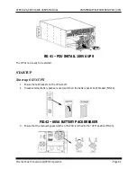
In case external battery packs are used, switch on the battery pack circuit breaker (FIG 51).
3.
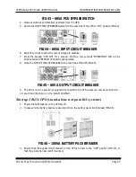
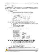
Ensure that the bypass circuit breaker on the UPS is turned to the “UPS” position (FIG 52), or
that the protection bar is still mounted.
4.
Close all switches and breakers upstream from the UPS.
5.
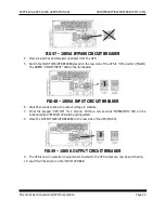
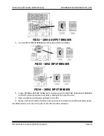
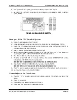
Switch the INPUT CIRCUIT BREAKER placed on the rear side of the UPS to “ON” position in
sequence (FIG 53). The GREEN “UTILITY INPUT” LED will be illuminated.
6.
Wait 45 seconds to allow the output voltage to stabilize.
7.
Press the keypad “UPS ON” for 1 second. Within a few seconds “OPERATION” LED will be
illuminated and “BYPASS” LED will be extinguished.
REPEAT STEPS FOR ADDITIONAL 10KVA UPS IN PARALLEL CONFIGURATION
8.
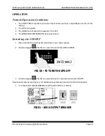
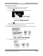
Close the OUTPUT CIRCUIT BREAKER on the rear side of the UPS (FIG 54).
REPEAT STEP FOR ADDITIONAL 10KVA UPS IN PARALLEL CONFIGURATION
9.
The UPS is now in operation; equipment connected to the UPS output can now be switched on.
10.
Load % will be shown on the “LOAD” LED BAR.
Normal Operation Conditions
1.
The UTILITY INPUT is present and within the tolerance as show in Specification section of this
manual.
2.
The UPS is turned ON.
3.
The LOAD does not exceed the capacity of the UPS.
4.
The OPERATING TEMPERATURE is below alarm level.

