background image

Xtreme Power Systems
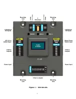
X24

Channel Expander

Installation And Usage Manual 

Supports: XtremeLink® RFU and Nano receivers

Futaba SBUS and SBUS2 receivers

Spektrum DSM2/DSMX satellite receivers

JR DMSS X-BUS receivers in Mode A or Mode B

JETI receivers in UDI mode

Graupner HoTT receivers in SUMD mode

Firmware v1.4

Manual v1.5

Revision Data: May 26

th

, 2017

1

Summary of Contents for X24

Page 1: ...pports XtremeLink RFU and Nano receivers Futaba SBUS and SBUS2 receivers Spektrum DSM2 DSMX satellite receivers JR DMSS X BUS receivers in Mode A or Mode B JETI receivers in UDI mode Graupner HoTT receivers in SUMD mode Firmware v1 4 Manual v1 5 Revision Data May 26th 2017 1 ...

Page 2: ...product returned without authorization will be refused returned without repair Liability You understand that by using this product you agree to hold XPS free from any type of liability either directly or indirectly Legal Information The look and feel and functionality of this product are protected by U S copyright laws Various terminology and feature names may be protected under U S trademark laws...

Page 3: ...HE MAIN SERIAL RECEIVER PORTS MAKE SURE YOUR SERVOS AND RECEIVERS ARE RATED TO HANDLE THE INPUT VOLTAGE THAT YOU POWER THE X24 WITH THE SPEKTRUM SATELLITE RECEIVER PORTS ARE ALWAYS POWERED WITH 3 3 VOLTS NO MATTER WHAT THE INPUT VOLTAGE IS Yes this is a rather advanced product Don t panic at first glance The X24 is capable of very complex programming but it s user interface is laid out so it is ea...

Page 4: ...uts one match power input and 24 servo outputs two of which are powered by the BEC power The LED is a RGB type allowing for virtually any color to be displayed Different colors and flashes are used to indicate various status conditions Receiver Inputs There are four main receiver inputs and four Spektrum compatible receiver inputs The main receiver inputs pass the input voltage directly to the rec...

Page 5: ...us of the system while operating The LED colors have various meanings Pulsating red no signal detected from receiver s Green connected with good voltage Yellow connected with voltage below the Minimum Voltage warning Purple connected with severe voltage problem below 3 5v Blue in the menu system Solid red in failsafe due to loss of RF link The brightness of the internal LED can be set using the LE...

Page 6: ...re being fully drained When you are not using the X24 for extended periods of time you should disconnect the main power inputs from the batteries Match Power If you purchased the version of the X24 that has current matching then the Match Power input will be used to provide power during the current match programming Normally this input is never used for anything other than the current matching how...

Page 7: ...d If not then fully insulate the unused set to prevent possible shorting Servo Outputs 22 of the 24 output ports will provide the main input voltage to the servos The remaining two output ports D2 and E2 provide the BEC voltage MAKE SURE YOUR SERVOS CAN HANDLE YOUR INPUT VOLTAGE The servo outputs occur virtually simultaneously to eliminate latency that commonly occurs in systems that output servos...

Page 8: ...Figure 1 X24 details 8 ...

Page 9: ...urations make sure that the batteries are the same type voltage and capacity Dual batteries are electrically connected in parallel so they will even out in voltage after being connected together over a period of time As soon as power is connected to the X24 it is on The only way to turn it off sleep mode is by using a switch that is plugged into one of the switch inputs or through the menu system ...

Page 10: ...Plug the other end of the female to female cable into the receiver s serial data port see the receiver manufacturer s documentation for details on where this port is located Note that by default Rx port 1 is the only port enabled You will need to enable all ports that you have receivers connected to and you must disable all ports where no receivers are connected For Spektrum satellite receivers co...

Page 11: ...or rudder PORT C1 channel 3 PORT C2 channel 3 PORT C3 channel 4 PORT C4 channel 4 PORT C5 channel 4 PORT C6 channel 4 PORT C7 channel 3 PORT C8 channel 3 Throttle ignition kill PORT D1 channel 1 PORT D2 channel 5 PORT E1 channel 1 PORT E2 channel 5 You can of course change the channel mapping for all output ports If you have a Futaba system it is recommended that you go to the SYSTEM MENU select R...

Page 12: ...e average input voltage updated in real time The number of receiver ports enabled is shown on the lower left and below that will be the number of lost frames The connection indicator is shown on the lower right and below that is the BEC status See Figure 2 below for details Figure 2 Main display screen At this point pressing the INC middle or DEC right buttons will cycle through the various inform...

Page 13: ...e occurs when NONE of the receivers acquired a valid packet of serial data during the programmed failsafe timeout period Voltage Information While are at the main display screen press the INC button to change to the Voltage Info screen See Figure 3 for details Figure 3 Voltage Info display screen The top voltage displayed is the minimum voltage that the X24 has seen since powered up or reset The m...

Page 14: ... giving you a true real time voltage display exposing every dip When you move servos this voltage will change dramatically After your flight you can look at the minimum and maximum values to see what changes occurred while you were flying Note The Minimum Voltage warning detection looks at the averaged voltage value not the absolute minimum real time voltage 14 ...

Page 15: ...d will enable automatic repeat of the INC or DEC function if that option allows it not all options have automatic repeat Pressing and holding the INC and DEC buttons at the same time for 3 seconds will reset the value to it s default value At the top left of the display screen is the exit go back symbol Pressing the ENTER button when this symbol is highlighted will go backwards one level in the me...

Page 16: ...Figure 4 Main Menu Figure 5 Main Menu w exit highlighted 16 ...

Page 17: ...Figure 6 Down arrow more entries available downwards Figure 7 Up Down arrow more entries are available both directions 17 ...

Page 18: ...Figure 8 Up arrow more entries available upwards 18 ...

Page 19: ...e Setup Menu options Output Ports this menu selects which channel appears on each output port along with the servo matching functions direction center and end points and type of servo Input Mode this menu selects the serial bus receiver protocol and failsafe functionality Receivers this menu selects which receiver ports are enabled or disabled BEC this menu selects the channel trigger point voltag...

Page 20: ... value ALL of the menu items below the Port menu item will change to reflect the value of the currently selected Port number Port numbers A1 A6 B1 B6 C1 C8 D1 D2 and E1 E2 can be selected and all settings for these ports can be changed The values being changed are done in real time If you have your transmitter on and the receiver s are connected changes to these items will be seen as you change th...

Page 21: ...or EPA H setting for you Changing the end point values is how you can manually match surfaces together The Servo setting allows you to set the Servo type to be either Digital or Analog The difference is the frame rate passed to the servo If you are using a fast frame rate radio under 20ms most analog servos will have a problem processing the fast update frame rate and this can lead to servo failur...

Page 22: ...tion on how to setup your receiver to output a serial protocol The Failesafe menu item allows you to change how the failsafes are handled when one occurs By default the X24 handles all failsafes itself It is possible that some receivers can provide failsafe data and that could be used instead If you need to have the receiver s control the failsafe output set the Failsafe to Rx Unless you have a se...

Page 23: ...rts Figure 11 Rx Ports menu The Rx Ports menu lets you enable turn On or disable turn Off each of the four serial ports Turn on any Port you want to connect a receiver to and turn off any Port that is not being used 23 ...

Page 24: ...if the Trigger value was 1500 then a servo channel value of 1501 or higher would turn on the BEC and 1499 or lower would turn off the BEC Selecting means to turn on the BEC when the trigger threshold is lower than the value set in Trigger The Trigger value is the servo pulse value used to determine when to turn On or Off the BEC when or is used The BEC s output voltage can be set to either 5v or 6...

Page 25: ...urn off when the BEC is disabled The LED can be a visual indicator for when the BEC is on which is handy when using the BEC to drive a gas engine ignition Note that during a system error condition low voltage or failsafe occurred the LED will flash to indicate a problem has occurred The state of the BEC does not affect the LED when a system error condition is detected 25 ...

Page 26: ...at port and allow you to then change those settings There are three failsafe types that are possible Hold means that during a failsafe condition the current output value will not change User means that the when a failsafe occurs the output port value will be set to the value show in Position Off means that the servo output for that port is turned completely off This is required for some auto pilot...

Page 27: ... you will have 10 seconds to move your transmitter sticks and switches to the position you want them to be during a failsafe condition Only ports set to a failsafe type of User will be affected Once the display shows Locked the settings are permanently saved 27 ...

Page 28: ... do any binding make sure that the Input Mode is set to Spektrum Mode the protocol used when binding Do Bind Start used to invoke binding There are four different possible protocols supported for the binding DMS2 22ms DSM2 11ms DSMX 22ms DSMX 11ms Consult your Spektrum manual to determine what protocols your transmitter and receiver can support Do Bind Start is a special option that starts the bin...

Page 29: ...Follow the instructions in your Spektrum transmitter manual for putting the transmitter into binding mode Once the binding has completed the system will be immediately ready for use 29 ...

Page 30: ...t allows you to perform a series of servo movements controlled by using just a single channel input Each sequencer has 5 stages and 3 positions The sequencer can be used for things such as gear door sequencing scale motion pilot turning head waving arms etc multiple release mechanisms folding wings w locks canopy slider etc A common example use is a split gear door setup where a door will open del...

Page 31: ...ection of the sequence When the channel value is lower than the Trigger value the sequence is moving from stage 5 to stage 1 position 3 to position 1 When the channel value is higher than the Trigger value the sequence is moving from stage 1 to stage 5 position 1 to position 3 Port is the output port used for the sequence If the sequencer is enabled then this port is controlled by the sequencer an...

Page 32: ...and 16 the sequence of event would go like this When channel 9 s value on power up is less than 1500us then the sequence is at Stage 1 and output port A4 s value is 1100us When channel 9 s value changes to a value that is greater than the Trigger position 1500us then the sequence starts moving from Stage 1 to stage 5 The first thing that happens is Stage 2 Delay 1 which in this case is 0 no delay ...

Page 33: ...ned to a sequencer does NOT change the position of a servo during a failsafe condition When a failsafe occurs the sequencers are frozen after completing the sequence if a sequence was occurring prior to the failsafe condition 33 ...

Page 34: ... system gives you the ability to automatically current match up to 12 pairs of master and slave servos During the AutoMatch procedure servos will be turned on and off as needed If a servo you are using has a failsafe feature built in it MUST be disabled in order to use the AutoMatch feature You should always disable servo failsafes anyways because failsafe control is one of the features that the X...

Page 35: ...TO OFF ONLY THE MASTER SERVO SHOULD BE CONTROLLING A SURFACE BEFORE DOING THE AUTOMATCH PROCESS ALL SLAVE SERVOS MUST BE OFF The AutoMatch function allows matching up to three slave servos per master in a single operation The AutoMatch setup defines which servo is to be the Master and which servo is to be used as a Slave Servo Groups are used to define the pairs of master and slave servos You can ...

Page 36: ...s before doing the AutoMatch and only plug in the servos as outlined below When you enter the AutoMatch mode all servos must be unplugged After selecting the Setup Master option plug in just the master servo make all of your adjustments unplug the master servo and then exit the Setup Master option After selecting the Setup Slave x where x is the slave number plug in just the slave servo make all o...

Page 37: ... will let you define all of the same parameters found in normal Output Port setup described above The menus and functions are the exact same so any changes here will also affect the Output Port setup as well While setting up the master only the servo defined by the Port can be moved using your transmitter All other servos are disabled while setting up the master servo Selecting the Setup Slave opt...

Page 38: ...ing the Dir item and toggling between N normal and R reverse modes You use the Center item to set the center offset of the slave servo to be as close as possible to the where the master servo s neutral position is It does not have to be perfect This is used just as a reference for the start of the current matching Make sure that your transmitter s stick position is centered while adjusting the cen...

Page 39: ...aster servo Only the master servo will move while this screen is shown Make sure you move your stick to the absolute maximum in each direction The channel values for Low and High will be shown This information is not needed and is only provided as a reference Once you are satisfied with the input range press the ENTER button Figure 22 AutoMatch Set Center 39 ...

Page 40: ...eference The matching process will take quite some time as the system builds up to a 1536 point match curve During the AutoMatch do not apply any pressure to the surfaces being matched Doing so will interfere with the matching process and give you inaccurate results For the best results it is recommended that you place all surfaces vertically when performing the AutoMatch If you abort the matching...

Page 41: ...also programmable Warnings this menu selects warnings and how they are handled Menu Limits this menu selects the minimum and maximum limits that are used for all of the various Setup menus Computer Mode this menu enters the computer programming mode using the Serial Link sold separately Information this menu shows information about the hardware options and firmware Reset Defaults this menu allows ...

Page 42: ...de switch normally open can be used with the X24 However there are two distinct differences from normal R C slide switch assembly and any slide switch used with the X24 First with a R C slide switch assembly the wiring typically passes through the switch assembly so each end has connectors an input from a battery to an output to your receiver The X24 needs a SPST type slide switch You will likely ...

Page 43: ...r changing the position of an external switch SW1 or SW2 will turn the X24 back on Remember the X24 is not actually off it is in a deep sleep mode and power should be removed from the X24 when your aircraft is being stored Figure 25 Switch wiring 43 ...

Page 44: ... When the input voltage drops below this voltage the LED will change to yellow If the input voltage drops below 3 5v the LED will change to purple The LED will remain this color when not in a menu system until the voltage is reset in the Voltage Info screen see Page 3 Voltage Information By default the external LED output will flash when there is a situation that results in a warning The warning f...

Page 45: ...ternal LED flashing you should look at the voltage information screen to see if a low voltage condition occurred If the voltage was good then the flashing is due to a failsafe that occurred during flight You can check the number of lost frames 45 ...

Page 46: ...menu currently has one option changing the brightness of the internal LED LED Level brightness level of the internal LED Range is from 1 to 255 with 255 being the brightest The LED can be very bright especially indoors so the level can be changed to suit your liking 46 ...

Page 47: ...alue for output port Only make changes to these values if you know what you are doing System Menu Computer Mode Selecting this mode goes to the computer programming mode The Serial Link sold separately is a USB interface that connects the X24 through the MATCH port FUNC 2 The Serial Link powers the X24 in this mode You MUST power off the X24 to get out of the computer programming mode WARNING ALL ...

Page 48: ... channel mapping Channel 1 throttle Channel 2 aileron Channel 3 elevator Channel 4 rudder Channels 5 various Futaba radio systems have the following channel mapping Channel 1 aileron Channel 2 elevator Channel 3 throttle Channel 4 rudder Channels 5 various Choose the mapping that matches your type of radio system by pressing the ENTER button when either selection is highlighted Note that the Input...

Page 49: ...about the X24 hardware options and installed firmware System Menu Power Off Selecting this option will power off the X24 This really puts the X24 into a deep sleep mode Pressing the ENTER button or moving the position of any external switch will turn the X24 back on 49 ...

Page 50: ...size screws or bolts You can use 4 size screws commonly used for mounting servos along with 4 size bounded rubber washers These will help with vibration If vibration is not a real concern then 6 size servo mounting screws can be used Optionally brass grommets used with servos can be used to take up extra space of the screw body Use a foam mounting pad in high vibration applications like gas engine...

Page 51: ...Figure 30 X24 Mounting pad template 51 3 30 2 08 ...

Page 52: ...25 throws the servo could move 125 of 400 which is 500 So 125 throws are 1000µs to 2000µs 150 of 400 is 600 So 150 throws are 900µs to 2100µs Center is always 1500µs except for Futaba which typically uses 1520µs Multiplex systems have a mode where center is 1400µs The X24 can increase your throw well beyond what a servo will handle especially if you have your transmitter s end points at 150 alread...

Page 53: ...and then a ramps down the power Without the PWM refresh the driver never outputs current to the motor and the servo s holding force goes away completely A digital servo updates the motor driver independently from the frame rate Some servos such as those used for tail rotors in helicopters update the motor driver every 3ms 333 times per second even though the frame rate may only be 22ms Most digita...

Reviews: