background image

Xtreme Power Systems


JR11x VERSION

(Internal RF Module Replacement)

Installation And Usage Manual 

XtremeLink

®

 is a registered trademark of Xtreme Power Systems

Firmware v3.10

Manual v1.0

Revision Date: October 1, 2013

1

Summary of Contents for XtremeLink JR11x

Page 1: ... Power Systems JR11x VERSION Internal RF Module Replacement Installation And Usage Manual XtremeLink is a registered trademark of Xtreme Power Systems Firmware v3 10 Manual v1 0 Revision Date October 1 2013 1 ...

Page 2: ...gh this manual you believe you cannot perform the installation please seek someone who can assist you This manual should provide ample information and clarity to install and use this product Warranty Information The XtremeLink system carries a limited lifetime warranty Units subject to improper installation misuse abuse crash damage or modifications will not be covered under this warranty Xtreme P...

Page 3: ...Legal Information The look and feel and functionality of this product are protected by U S copyright laws Various terminology and feature names are protected under U S trademark laws 3 ...

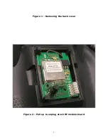
Page 4: ...l height of the cover so it will take some effort to remove the cover See Figure 1 Set the cover aside It is no longer needed Pull up on the entire RF module just enough so that it becomes unplugged from the transmitter See Figure 2 Locate the stock RF antenna connector and carefully remove the connector from the stock RF board by pulling straight up not at an angle DO NOT pull on the coax cable g...

Page 5: ...Figure 1 Removing the back cover Figure 2 Pull up to unplug stock RF module board 5 ...

Page 6: ...Figure 3 Remove antenna connector from the RF board 6 ...

Page 7: ...Figure 4 Remove RF board assembly 7 ...

Page 8: ...Figure 5 Empty RF module location 8 ...

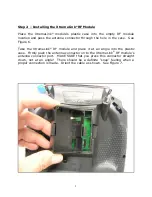
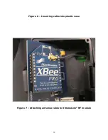
Page 9: ...the case See Figure 6 Take the XtremeLink RF module and place it at an angle into the plastic case Firmly push the antenna connector on to the XtremeLink RF module s antenna connector port MAKE SURE that you press this connector straight down not at an angle There should be a definite snap feeling when a proper connection is made Orient the cable as shown See Figure 7 9 ...

Page 10: ...Figure 6 Inserting cable into plastic case Figure 7 Attaching antenna cable to XtremeLink RF module 10 ...

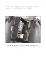
Page 11: ...With the cable routed properly position the XtremeLink RF module completely into the base of the plastic case See Figure 8 Figure 8 Put the XtremeLink RF module fully into plastic case 11 ...

Page 12: ...e push button switch passes through the hole labeled PROG The bottom of the lid has two tangs that will need to be snapped into the case With the lid fully over top of the case press on the bottom of the lid until it snaps flush with the case See Figures 9 and 10 for details Figure 9 Set the lid over top of the plastic case 12 ...

Page 13: ...Figure 10 Apply pressure to snap the lid flush with the case 13 ...

Page 14: ...ully rotate the plastic case and set it in the place MAKE SURE that the RF cable is not being pinched There should be plenty of space for the RF cable to slide inside of the RF module enclosure as it is rotated See Figure 11 Figure 11 Set module assembly in place 14 ...

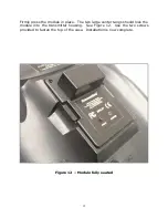
Page 15: ...e in place The two large center tangs should lock the module into the transmitter housing See Figure 12 Use the two screws provided to fasten the top of the case Installation is now complete Figure 12 Module fully seated 15 ...

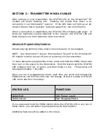
Page 16: ...TE Any XtremeLink receiver that has been bound to the XtremeLink RF module must be turned off prior to powering on the transmitter To enter advanced programming mode press and hold the PROG button and then turn on the power to the transmitter Hold the button until the STATUS LED changes from off to green and then finally to red This process will take approximately 7 seconds Once you are in program...

Page 17: ... and release the PROG button just once If you wanted the power level to be 3 you would press and release the button three times If you do not press the PROG button within five seconds or if the value you enter exceeds what is allowed the STATUS LED will alternately flash red and green error condition occurred and no change will be made At this point you are back at the programming mode start where...

Page 18: ...ly flash red and green error condition occurred and no change will be made At this point you are back at the programming mode start where you can select a programming option If you do make a change the STATUS LED will blink green red orange in rapid succession to let you know that the change was successful Below is a table of available hopping modes Hopping Mode Setting Single frequency w predicti...

Page 19: ... the binding plug to the port labeled B When the STATUS LED will turns solid red remove the binding plug The STATUS LED will then flash red at a different rate indicating that it is in binding mode Transmitter Press and hold the PROG button the XtremeLink RF module while powering on the transmitter Hold the button until the STATUS LED changes from off to green and then release the PROG button The ...

Page 20: ...O OR MORE RECEIVERS ARE TURNED ON AT THE SAME TIME AND THE TRANSMITTER IS THEN TURNED ON ANY OF THE RECEIVERS MAY LOCK ON TO THE TRANSMITTER THE OTHER RECEIVERS WILL NOT LOCK UNLESS SET AS A SLAVE TURNING ON AND OFF YOUR TRANSMITTER WILL CAUSE RECEIVERS TO LOCK AND UNLOCK FOR THIS REASON PLEASE MAKE SURE THAT YOUR LAST MODEL IS TURNED OFF BEFORE FLYING THE NEXT MODEL ALTHOUGH THIS IS THE SAME BEHA...

Page 21: ...ks until there is intermittent control Releasing the PROG button should restore 100 control If it does not do not use the system and contact Xtreme Power Systems for assistance 8 Test complete Range test for original surface or park flyer receivers Follow the instructions of above The range test will be limited to approximately 35 feet instead of at least 125 feet for full range receivers WARNING ...

Reviews: