Xtreme Power Conversion Corporation
M90U-80 & 140 User’s Manual
Page 64
Uninterruptible Power Supply
21
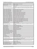
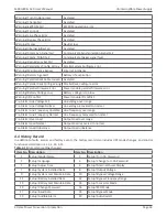
Setup! Factory Reset
22
Setup! Cold Start
23
Setup! EEPROM Reset
24
Setup! Battery Mode Delay Time
25
Setup! EPO Function
26
Setup! Shutdown Restore Time
27
Setup! Save Setting
28
Setup! Redundancy
29
Setup! Power Rating Setting
30
Setup! Charger Test
31
Setup! Nominal Battery Voltage
32
Setup! Battery Capacity in Ah
33
Setup! Maximum Charging Current
34
Setup! Battery Low Voltage
35
Setup! Battery Low Capacity
36
Setup! Battery Shutdown Voltage
37
Setup! Periodic Battery Test
38
Setup! Stop By Time
39
Setup! BATTERY Age Alert
40
Setup! Temperature Compensation
41
Setup! Charging Voltage
42
Setup! PRE-ALARM
43
Setup! UPS Parallel
44
Setup! Independent Battery
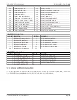
Table 4-14:
UPS mode change
Item No. Description
Item No.
Description
1
UPS Mode! Power On Mode
2
UPS Mode! Standby Mode
3
UPS Mode! Bypass Mode
4
UPS Mode! Line Mode
5
UPS Mode! Battery Mode
6
UPS Mode! Battery Test Mode
7
UPS Mode! Fault Mode
8
UPS Mode! Converter Mode
9
UPS Mode! ECO Mode
10
UPS Mode! Shutdown Mode
11
UPS Mode! Un-Connection
12
Table 4-15:
Control execution
Item No. Description
Item No.
Description
1
Control! System Turn On
2
Control! System Turn Off
3
Control! Manual Battery Test
4
Control! Cancel Battery Test
5
Control! Turn To Bypass
6
Control! Shutdown Restore
7
Control! Cancel Shutdown
8
Control! Charger Turn On
9
Control! Charger Turn Off
10
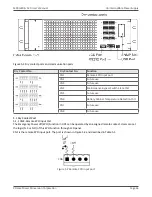
5. Interface and Communication
As shown in figure 5-1, the Static Transfer Switch (STS) Module includes dry contact Ports (CN1~CN8), Extra Comm.
Slot, SNMP Slot and communication port (RS232 Port, USB port) on the front panel.

