Xtreme Power Conversion Corporation
TX90 6kVA & 10kVA Service Manual
Page 11
Uninterruptible Power Supply
L11 NOT USED:
all systems are single input
N1, L12, G1:
the terminals for utility input with single input connection
G1:
the terminal for UPS input ground
N1:
line 1 (L1) input
L12:
line 2 (L2) input
G2, N22, L22, N21, L23, L21:
the terminals for UPS output, see below output options for configuration details
G2:
the terminal for UPS output ground
Remarks:
1. The maximum current for each terminal is 30 Amps for 6 kVA, 50 Amps for 10 kVA.
2. The UPS is always a Single Input configuration. The Dual Input configuration is not used. The AC source can
be 208V or 240V landed to the L12 and N1 terminals.
3. Use No. 6 AWG, 75°C minimum copper wire and 23 lb-in Torque force when connecting to terminal block.
4. The transformer has two input voltage options, 208V and 240V. If the input is configured at 208V but the
actual input is 240V, then the output voltages will boost up 15%.
Input Configuration
208V input applications:
208V input with a 120/240V output is the default for these systems. This means the in-
verter output is programmed to 208V and the output transformer primary tap is set to the 208V setting. These are
the default settings for this system. Please refer to output Option 1 in this section.
240V input applications:
If the input voltage is 240V, the following steps must be performed to obtain a 120/240V
output with a 240V input.
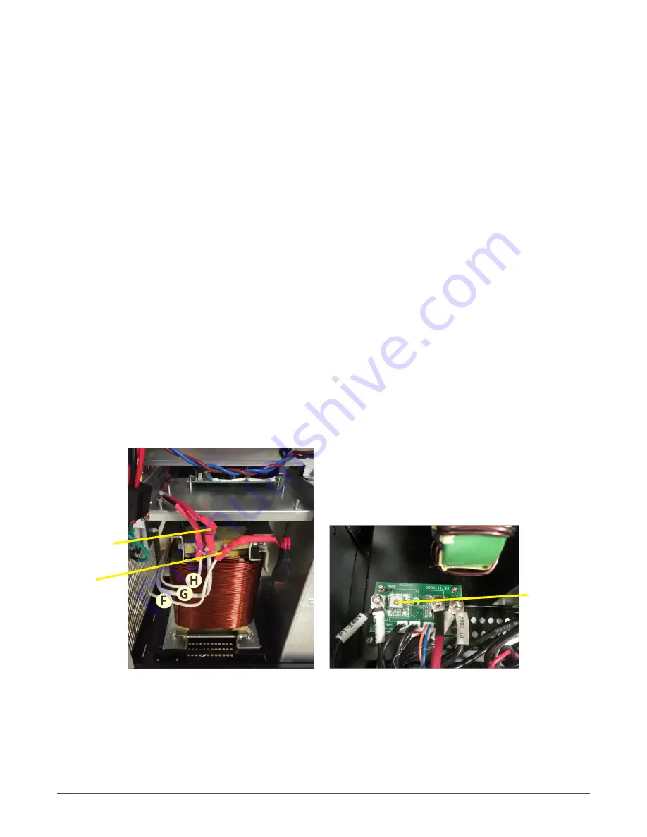
1. With no AC applied to the unit, change the transformer primary tap from 208V default setting to 240V
shown below. Access to tap settings is gained by removing the side covers.
TX90-6K Input Taps
TX90-10K Input Tap Board
2. The UPS inverter output voltage must also be programmed to 240V. Refer to the Changing the UPS Default
Settings section for more details. Option 1 below provides a 120/240V output with a 240V input.
Move red
wire to here
when there is
a 240V input
Tap shown
on the 208V
setting
240V tap


