5. Interface and Communication
5.1 Dry Contact Port
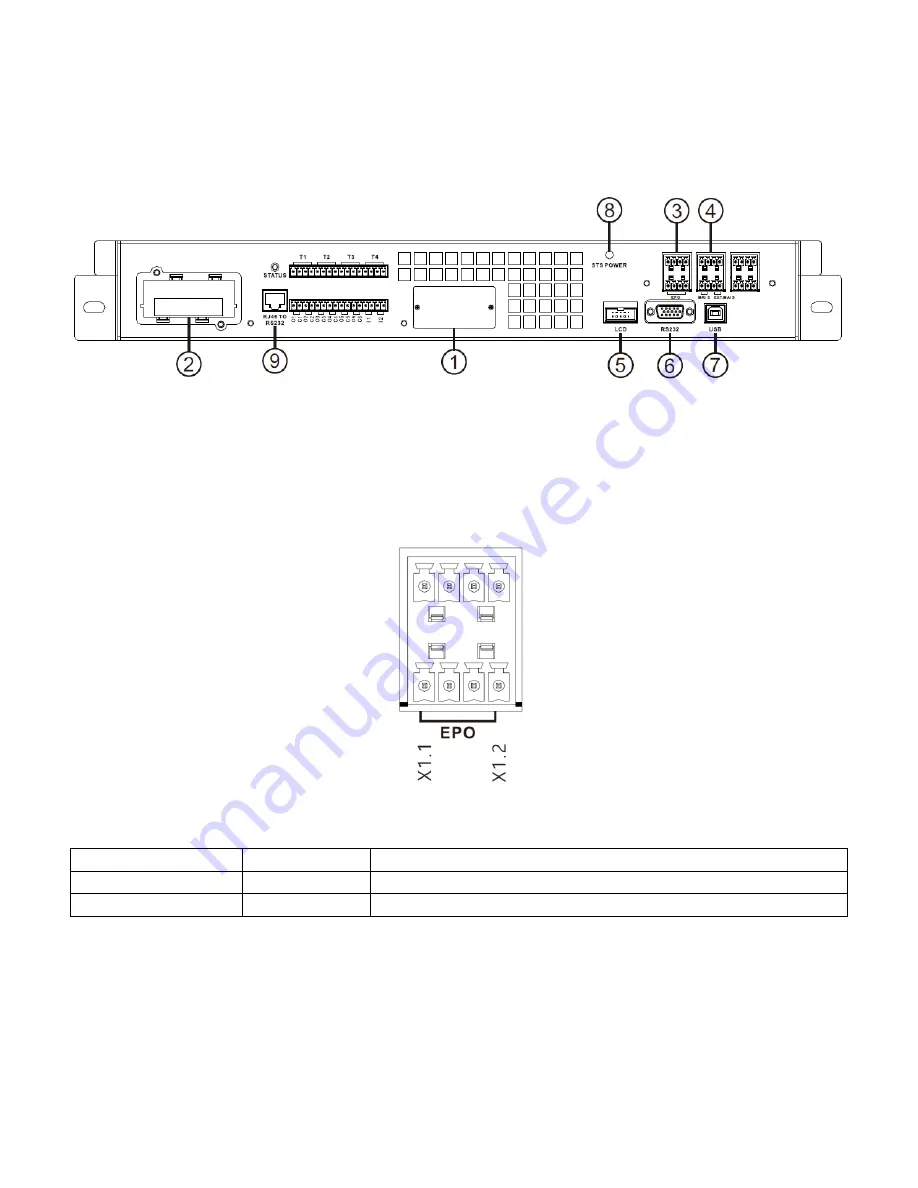
As shown in figure 5-1, the Monitor Module includes dry contact ports (
③
~
④
), Extra Comm. slot,
SNMP slot, LCD connection port, STS Power LED and serial communication ports (RS232 port, USB
port, RJ45 to RS232 port) on the front panel.
Figure 5-1 Front view of Monitor module
5.1.1 X1-Remote EPO Input Port
The Emergency Power off (EPO) function in UPS can be operated by an assigned remote contact.
Logic N.C. turns off the UPS.
X1 is the remote EPO input port. The port is shown in Figure 5-2 and described in
Table 5-1
.
Figure 5-2 Remote EPO input port
Table 5-1:
Description of remote EPO port
EPO Logic Setting
Position
Description
Short
X1.1 & X1.2
EPO is not activated when X1.1 & X1.2 shortened
Open
X1.1 & X1.2
EPO is activated when X1.1 & X1.2 opened
EPO Logic setting is Normal Closed (N.C), EPO is triggered when pins 1 and 2 of X1 are opened.
Note:
1.
EPO function activates shutdown of the rectifiers, inverters and static transfer switch. But it
does not internally disconnect the input power supply.
5.1.2 X4-Maintenance Bypass Switch State Port
X4 is the maintenance bypass switch port. The port is shown in Figure 5-3 and described in
Table
Summary of Contents for X90-2S
Page 12: ...2 6 1 Mechanical Data Dimensions Width Depth Height 600mm 1065m 2010mm Figure 2 8 Dimensions...
Page 15: ...Figure 2 13 Terminal Blocks...
Page 17: ...Off There is neither a fault nor an alarm...
Page 22: ......
Page 37: ......
Page 39: ...Step 7 Switch ON the output breaker Q3 AC startup procedure is complete...
Page 42: ......
Page 53: ...Figure 4 6 Control screen page...
Page 55: ...Figure 4 9 System Measurement Screens...
Page 56: ...Figure 4 10 Module Measurement Screens...
Page 88: ......


