Xtreme Power Conversion Corporation
XBDM-1520RHW User’s Manual
Page 11
Bypass Distribution Module
Wiring and Connecting
Initial Connection
1.
The XBDM-15RHW/XBDM-20RHW is a hardwired input and output Bypass Distribution Module. It must be
installed in conjunction with all local electrical codes, with work performed by a licensed electrician.
2.
All connections should be completed prior to providing input utility power to the XBDM-15RHW/XBDM-
20RHW.
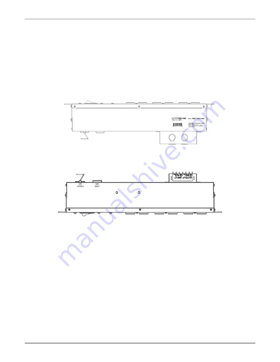
3. Input and Output wiring to the XBDM-15RHW/XBDM-20RHW should be routed through the terminal box
knock-out as shown in figure 12. The terminal box cover can be removed for ease of conduit connection and
wire routing.
XBDM-15RHW/XBDM-20RHW Input and Output Routing
4.
Please refer to the drawing below for input and output wiring terminal locations.
XBDM-15RHW/XBDM-20RHW Terminal Block View
Startup Sequence
1.
Turn the UPS OFF in accordance with UPS manufacturers’ documentation. Verify the correct wiring to the
XBDM prior to proceeding to step 2.
2.
Unplug the UPS from utility source. Depending on the model of UPS it may take a few seconds for the UPS
to completely shut down. All indicators on the UPS front panel should shutdown.
3. Disconnect the protected equipment power cord(s) from the UPS.
4.
Verify that the BYPASS switch on the XBDM is in the UPS position.
5.
Energize the circuit breaker providing input utility to the XBDM-15RHW/XBDM-20RHW from a properly
sized distribution panel.
The orange bypass available light should illuminate on the Bypass Distribution Module.
6. Plug the UPS INPUT cord into the 5-20R receptacle labeled FOR UPS INPUT on the rear of the XBDM-
15RHW/XBDM-20RHW.
7. Connect the UPS output receptacle to the XBDM-15RHW/XBDM-20RHW C20 plug labeled UPS OUTPUT
using the appropriate 15 or 20A cord supplied with the XBDM-15RHW/XBDM-20RHW.
8. Assure that the distribution for the loads to be connected to the XBDM-15RHW/XBDM-20RHW is properly
connected to the XBDM-15RHW/XBDM-20RHW.


