background image

Operation Manual

57

www.XMFG.com

Operation

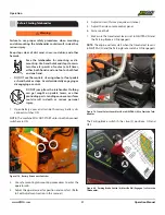
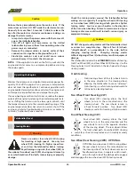
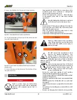
NOTE:    The fuel tank capacity is 48 gallons (181 L).

Make sure the telehandler is level to obtain an accurate

fuel level reading.

Shut off the engine.

Ground the fuel nozzle against the filler neck to avoid

sparks.

Fuel Types 

Use ASTM #2 diesel fuel with a minimum Cetane rating of 

40 for better fuel economy and performance under most 

operating conditions.

Use standard #2 diesel fuel for operating at temperatures

above 32°F (0°C).

Use a blend of #1 and #2 diesel fuel (“winterized” #2 diesel) 

for operating at temperatures below 32°F (0°C).

Fuels with Cetane ratings higher than 40 may be needed

in higher altitude or in an extremely low temperature

climate to prevent hard starts and excessive smoke.

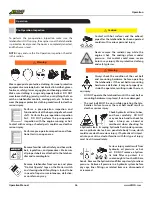
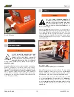
Engine fuel is flammable and 

can  cause a fire or  explosion 

resulting   in   death  or   serious  

injury. DO NOT smoke while 

refueling and keep sparks and 

open flames away from the telehandler.

Warning

Refueling 

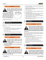
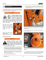
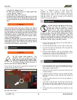
Pintle Hook

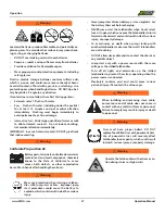
Death or serious injury could result from im-

proper operation when using tow connection. 

Do not elevate boom above 30 degrees when 

towing. Do not exceed rated tow capacity (500 

lbs vertical load, 5,000 lbs tow capacity. 

The Pintle Hook is used for towing trailers and equipment, rat-

ed at or below 5,000 lbs maximum capacity. Failure to comply 

with this capacity limitation, or elevating the boom above 30 

degrees when towing could result in death or serious injury.

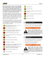
Engine Protection System

The engine is equipped with an engine protection system. The 

system monitors critical engine temperatures and pressures, 

and logs diagnostic faults when an over or under normal con-

dition occurs. If an out-of-range condition exists and engine 

derate action is to be initiated, the operator is alerted by an 

in-cab WARNING message. 

NOTE:   Engine power and speed will gradually be reduced, 

depending on the level of severity of the observed condition. 

The engine protection system will not shut down the engine 

unless the engine protection shutdown feature has been en-

abled.

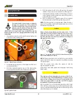
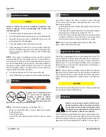
Shut Down Procedure 

1. Park telehandler on level ground, if possible.
2. Stop the telehandler by applying the service brake pedal.
3. Place the travel select lever in NEUTRAL (N) and set the

parking brake to ON (engaged).

4. Lower the boom and rest carriage on ground.
5. Allow the engine to idle 3 to 5 minutes before shutting it

off after a full-load operation. This allows adequate cool

down of pistons, cylinders, bearings, and turbocharger

components.

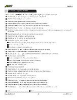
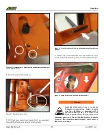
Caution

Failure to follow the correct shutdown procedure may 

result in damage to the turbocharger and shorten the 

turbocharger life.

NOTE:  The engine is equipped with an electronic control 

module (ECM). Ensure the Ignition Switch is turned off for a 

minimum of 100 seconds prior to disconnecting the continu-

ous (unswitched) battery power supply. If the unswitched bat-

tery power supply is disconnected in less than 100 seconds 

after the Ignition Switch is turned off active fault codes and 

incorrect ECM information can occur.
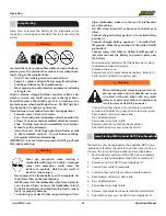
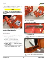
6. Turn the ignition key to OFF and remove the key.
7. If the telehandler is parked on an incline, block the wheels.

NOTE: The engine is equipped with a lubricity filter that 

allows military JP8 fuel to be used. 

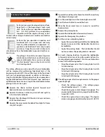
Caution

Do not idle for extended periods of time. Excessive idle time 

can cause poor engine performance.

Summary of Contents for XR1045 Alden TIER4

Page 1: ...www XMFG com Operation and Safety Manual QRGOVSALES XR1045 Alden TIER4 CONTRACT SP4510 17 A 0002 24905 002 20 ...

Page 2: ... Steering Select Switch 40 Boom Control 40 Attachment Tilt Switch 41 Frame Sway Control 42 Auxiliary Attachment Control 42 Fork Positioning Carriage Operation 43 Work Lights 43 Wiper 44 Boom Angle Indicator 44 Boom Extend Letters 44 Frame Level Indicator 44 Telehandler Lifting Points 45 Operation Pre Operation Inspection 46 Pre Operation Inspection Checklist 48 Functional Tests 49 Operator Mainten...

Page 3: ...f telehandler controls in a safe clear area BEFORE you operate this telehandler on a work site It is your responsibility to observe applicable laws and regulations and to follow manufacturer s instructions on telehandler operation and maintenance When contacting our parts department please have the telehandler serial number available The serial number plate is located in the operator s cab at the ...

Page 4: ...ds Safety Disclaimer Safety Symbols Safety Safety symbols are provided to remind the operator of hazardous situations Xtreme Manufacturing provides these symbols in an attempt to inform all operators regardless of reading and language skills of as many potential hazards as possible These symbols cover many but not all potential dangers and hazards associated with operating the telehandler Make saf...

Page 5: ...Operate If Using Alcohol Drugs Or Medications Personal Protective Equipment Safety Shoes Lead Acid Batteries Create Explosive Gases Warning Hydraulic Oil Under Pressure Hot Oil DO NOT Open Unless Cap Is Cool To Touch Warning Rotating Belts Can Cut Or Entangle Replace Worn And Illegible Safety Labels And Labels Read Maintenance Manual Before Working On This Telehandler Know First Aid Instructions A...

Page 6: ...ng Telehandler Tip Over Can Cause Death Or Serious Injury DO NOT Raise Boom While Traveling On A Slope Danger Keep A Safe Distance From Electrical Lines Pinch Points Hands DO NOT Use Ether As A Starting Aid DO NOT Allow Riders On Auxiliary Attachments Set Parking Brake To OFF Disengage Parking Brake DO NOT Jump If TelehandlerTips Keep Seat belt ON And Brace Yourself Tip Over Hazard Especially Trav...

Page 7: ...ation or alter ation including welding or drilling can impair and weaken the protective capability of the Rollover Protective Structure Falling Object Protective Structure ROPS FOPS and could result in death or serious injury Replace the ROPS FOPS if it is damaged before operating the telehandler Under Occupational Safety and Health Administration OSHA rules employers are required to train workers...

Page 8: ...ts could cause death or serious in jury Warning Operate the telehandler only on firm stable surfaces Holes obstructions debris loose fill and other work site hazards could result in death or serious injury DO NOT allow bystanders in the work area Avoid personnel machinery and telehandlers in the work area Knowtherulesformovementofpeopleandtelehandlers on the work site Follow work site signs and si...

Page 9: ...nd remain legible A brief description of controls indicators and instruments is provided as a convenience for the operator These descriptions DO NOT provide complete operation instructions Read and understand the entire manual to prevent death serious injury or equipment damage Keep fingers and feet away from moving parts or pinch points to prevent pinching or crushing DO NOT allow anyone between ...

Page 10: ...ct lever in NEUTRAL the Park ing Brake switch ON engaged and the service brakes ap plied BEFORE starting the telehandler The seat belt MUST be worn while operating the telehandler Failure to wear the seat belt could result in death or serious injury DO NOT adjust the seat or seat belt while the telehandler is moving Keep both hands on the wheel while the telehandler is moving to prevent loss of te...

Page 11: ...T raise the boom while operating on a slope Raising the boom on a slope even with out a load will change the cen ter of gravity could cause a tip over and result in death or serious injury DO NOT turn on a steep slope DO NOT drive the telehandler across slopes Always drive the telehandler straight up and down a slope never drive diagonally up or down a slope Drive the telehandler forward up a slop...

Page 12: ...r structural damage which could result in death or serious injury Attachments Warning Improper connection of an auxiliary attachment could result in death or serious injury Attachments not locked into place can become unstable and fall on the operator or other personnel near the telehandler Make sure attachment locking devices are always in place DO NOT operate the telehandler until you have posit...

Page 13: ...cking for a hydraulic leak Escaping hydraulic fluid under pressure even a pinhole size leak can penetrate body tissue which could cause death or serious injury If hydraulic oil is inject ed into your skin a doctor familiar with this type of injury must treat it immediately Warning Serious injury could result from hydraulic oil pressure or hot oil DO NOT remove a hydrau lic tank filler cap unless i...

Page 14: ...internal contact DO NOT give fluids that induce vomiting Batteryposts terminals andrelatedaccessories contain lead and lead compounds chemicals known to the State of California to cause cancer birth defects or other reproductive harm Wash hands after handling these items Warning California Proposition 65 Warning Wear eye protection when starting a telehandler with jump start cables Improper jump s...

Page 15: ... 4 NOTE The minimum release pressure is 435 psi The maxi mum release pressure is 653 psi Parking Brake Manual Release 4 Remove the hydraulic hose connected to one port 5 Connect a manual HP hydraulic pump to the parking brake ports using a threaded coupling 9 16 18 UNF and a collector bottle as shown in Figure 5 6 Apply hydraulic pressure using the manual hydraulic pump to release the brake 7 Tore...

Page 16: ...t Side View Right Side View Figure 6 Label Legend Left Cab Side Figure 7 Label Legend Right Hydraulic Tank Side Labels 58 Front View Figure 8 Label Legend Front Figure 10 Label Legend Cab Rear View Figure 9 Label Legend Rear 50 42 49 12 Cab View ...

Page 17: ...039 000 DECAL XRM ANGLE INDICATOR 1 25 18041 001 LABEL WARNING PINCH POINT 6 26 18042 000 DECAL XID XTREME SMALL GRN 3 27 18043 000 DECAL XID XTREME MED GRN 2 Table 1 Labels 28 18044 000 DECAL XID X GRN 3 29 18046 000 DECAL LH SWOOSH 1 GRN 1 30 18047 000 DECAL LH SWOOSH 2 GRN 1 31 18048 000 DECAL RH SWOOSH 1 GRN 1 32 18049 000 DECAL RH SWOOSH 2 GRN 1 33 18053 000 DECAL BOOM 1045 ABCD 1 34 18054 00...

Page 18: ...18004 060 702 636 2969 800 497 1704 www XMFG com Parking Brake OFF ON Steering 4W 2W Crab Front and Rear Wheels Must Be Centered Before Engaging Hazard Turn Wiper Wash On Off Boom Rear Front On Off Lights Outriggers Up Down Left Right Replacement labels may be obtained by contacting Xtreme Manufacturing at 702 636 2969 From outside Las Vegas Nev call Xtreme Manufacturing toll free at 800 497 1704 ...

Page 19: ...Operation Manual 19 www XMFG com Labels 11 18018 002 12 18019 001 9 18017 001 10 18018 001 13 18020 001 14 18021 001 15 18022 001 16 18023 001 ...

Page 20: ...Operation Manual 20 www XMFG com Labels 17 18025 001 18 18026 001 19 18027 001 20 18031 001 23 18347 000 24 18039 000 21 18032 001 WARNING 22 18033 000 AUX A AUX B FRONT HANDLE OPERATION 18347 000R01 ...

Page 21: ...Operation Manual 21 www XMFG com Labels 25 18041 001 26 18042 000 29 18046 000 30 18047 000 27 18043 000 28 18044 000 31 18048 000 32 18049 000 ...

Page 22: ...peration Manual 22 www XMFG com Labels A D 18053 000 B C E 18054 000 F 33 18053 000 34 18054 000 G 18055 000 H 35 18055 000 36 18066 001 FULL 18069 000 37 18067 100 38 18069 000 39 18070 001 40 18081 000 ...

Page 23: ...Operation Manual 23 www XMFG com Labels 41 18082 001 42 18083 001 43 18086 001 44 18090 001 45 18300 001 46 18311 000 47 18312 000 18311 000 48 18315 000 ...

Page 24: ...ONING CARRIAGE 72 INCH MAXIMUM FORK LENGTH 5 000 LBS AT 24 IN MIN CAPACITY FORK 10 000 LBS PAIR P N 17444 000 LOAD RATINGS ARE FOR VEHICLE EQUIPPED WITH FOAM FILLED OR SOLID TIRES LOAD RATING INCLUDES WEIGHT OF ANY RIGGING 51 17444 000 53 18334 005 DAMAGE may result from adjusting forks when carriage is loaded CARRIAGE DAMAGE ONLY ADJUST FORKS WHEN CARRIAGE IS UNLOADED 18331 000 18332 000 DEATH or...

Page 25: ...level indicator 3600 visibility Tires G2 Foam filled Features Optional Equipment Feature Description Options Enclosed cab with heat and air conditioning Heater defroster windshield wiper Work light package Hydraulic side swing carriage with quick attach couplers Various carriage sizes Full line of attachments Turn signals hazard lights MIL Std 209 tie downs and lifting points Fire Extinguisher mou...

Page 26: ...earance 16 5 Turning Radius 12 Standard Equipment Heavy duty Frame Chassis Heavy duty Roller Boom Melonite Pins and Rollers Direct Dual Control Hydraulic Valve Actuation Robust Wiring No Spades No Pins Rear Axle Stabilization RAS Center Inline Engine Drive Train Full time Planetary 4 Wheel Drive Steering 4 Wheel Circle Crab 2 Wheel Front Limited Slip Diferential Back Up Alarm Open ROPS FOPS Adjust...

Page 27: ...ual 27 www XMFG com Major Components 18 Figure 11 Right Hydraulic Tank Side View With Optional Mil Std 209 Lifting Lugs Figure 12 Left Cab Side View With Optional Mil Std 209 Lifting Lugs Major Components Side View ...

Page 28: ...Operation Manual 28 www XMFG com Major Components 17 16 22 21 17 16 14 21 Figure 13 Rear Left Quarter View Figure 14 Rear Right Quarter View Rear View Left Rear View Right ...

Page 29: ...ont Cover 10 Lift Hook 11 Attachment Major Standard Components Item Description 12 Enclosed Cabin ROPS FOPS 13 Fuel Tank Diesel 14 MIL Std 209 Tie Downs Lifting Lugs Optional 15 Boom Angle Indicator 16 Battery Cover 17 Pintle Hook 18 Radiator Cover 19 Front Frame Sway Cylinder 20 Attachment Quick Disconnect 21 Dual Battery Disconnect Switch under item 16 22 Counterweight Figure 15 Front View Major...

Page 30: ...em except the horn and accessory outlet RUN All controls and indicators are operable START Engages starter motor to crank engine NOTE The START position is spring loaded When the knob is released the Ignition switch will automatically return to the RUN position Accessory Outlet A 12 Volt accessory outlet is provided as a power source for personal items such as a radio or cell phone Figure 17 12 V ...

Page 31: ...ls The operator seat can be adjusted four 4 ways weight suspension lumbar support fore and aft and backrest angle Figure 23 Operator Seat Operator Seat Fire Extinguisher Optional The fire extinguisher is located behind the operator seat Figure 21 Fire Extinguisher A B Figure 22 Emergency Stop Button Emergency Stop Optional The optional Emergency Stop cuts the power from the bat tery turning the fo...

Page 32: ...t level desired Figure 24 Weight Suspension Lever Fore and Aft Adjustment Lever Pull the fore and aft adjustment lever outward from the seat to release the seat lock Slide the seat forward or backward to a comfortable location and release the lever to lock the seat in the desired position Figure 26 Fore and Aft Adjustment Lever Backrest Angle Adjustment Lever Pull the backrest angle adjustment lev...

Page 33: ...ard two inch 2 wide retractable seat belt A three inch 3 wide retractable seat belt is available where required by local laws and regulations Figure 28 Retractable Seat Belt Warning DO NOT adjust the seat or seat belt while the telehandler is moving Keep both hands on the wheel while the telehandler is moving to prevent loss of telehandler control which could result in death or serious injury Befo...

Page 34: ...s three 3 positions FORWARD NEUTRAL and REVERSE which change the direction of travel Controls and Indicators Travel Select Lever Position Purpose F Forward UP Position away from the operator N Neutral CENTER Position R Reverse DOWN Position toward the operator The travel select lever automatically locks when it is in the NEUTRAL position The operator must raise and move the travelselectleverwhench...

Page 35: ... A B Load Capacity Charts The Load Capacity Charts are located on the left side of the front control panel The Load Capacity Charts are provided to assist the operator in determining how to safely handle loads with the telehandler including boom angle height and reach Figure 35 Load Capacity Charts Display Indicators The display allows the operator to view vital engine information and other critic...

Page 36: ...or turns red shows oil pressure below 10psi and the Oil Pressure Warning red is displayed stop the telehandler follow proper shut down procedures tag telehandler with Do Not Operate tags and have a qualified mechanic service or repair the telehandler BEFORE placing it into service again K REAR AXLE CENTERED INDICATOR Illuminates when the rear wheels are centered L DIRECTION OF TRAVEL INDICATOR Dis...

Page 37: ...dicatormonitorsanddisplays the oil temperature within the transmission At normal operating temperature it stays green Between 215 and 224 0F it turns yellow to warn that the transmission operates above the recommended temperature range When the transmission oil temperature reaches 2250F the display turns red to indicate an overheating situation Soft Buttons Soft Buttons Menu Button Enter Button UT...

Page 38: ...displays a green check symbol to the right of the condition if it is met Figure 45 Calibration Machine Conditions Check Figure 46 Clutch Calibration When all of the machine conditions for calibration are met the TCU enters clutch calibration mode The TCU starts calibrating the first clutch and upon successful calibration it moves to the second clutch and so forth until the last one is calibrated T...

Page 39: ... button will enter a mode where some display settings may be adjusted using the Up Down buttons Figure 50 User Settings Figure 47 First Clutch Calibration Successful The default settings can be restored using the top left button Each Restore Defaults needs to be confirmed or canceled on the next screen Pressing the MENU button will return to the previous menu Figure 51 Diagnostics Menu CLEAR ALL F...

Page 40: ...speed control Function speed is proportional to handle movement The more the handle is moved in the appropriate direction the faster the corresponding function will occur NOTE Increasing engine speed can increase boom lift and extend speed Figure 53 Boom Control Joystick Steering Select The Steering Select switch has three 3 steering positions Crab TwoWheel Steering 2W and FourWheel Steering 4W Fi...

Page 41: ...tional tohowfartheswitchisrolled Themoretheswitchisrolled in the appropriate direction the faster the corresponding function will occur Attachment Tilt Switch Intended Action What To Do Tilt attachment down Roll tilt switch upward A away from the operator Tilt attachment up Roll tilt switch downward B to ward the operator A B C D E F G H Figure 55 Boom Control Joystick Functions 2 Theattachmentcar...

Page 42: ... operation Figure 59 Auxiliary Attachment Control Lever Figure 58 Frame Sway Override Switch Yellow A and Horn Button Red B NOTE Lock the frame sway by placing the travel select lever in NEUTRAL or applying the service or parking brake NOTE Maximum frame sway is 220 overall or 110 each direction left and right The frame sway feature becomes locked and will not operate when the boom is raised 40 or...

Page 43: ...ways use the Fork Po sitioning control handle to adjust the forks BEFORE loading the carriage Figure 60 Fork Positioning Control Handle 1 2 3 The yellow buttons 1 and 2 on the Boom Control Joystick are NOT OPERATIONAL IN FORK POSITIONING this function is accomplished by the Auxiliary Attachment Control lever To move the forks outward move the auxiliary handle 3 to the left to move the forks inward...

Page 44: ...to 700 Figure 64 Boom Angle Indicator Frame Level Indicator The frame level indicator is mounted on the upper right corner of the operator s cab The frame level indicator allows the operator to view if the telehandler has been positioned in a level condition Figure 66 Frame Level Indicator Boom Extend Letters As the boom is extended the boom extend letters on the left side of the boom are visible ...

Page 45: ...d if lifting points are installed Warning Ensure that no one is in the work radius before lifting tele handler to avoid crushing hazard Figure 69 XR1045 24V Optional MIL Std 209 Front Lifting Points Figure 70 XR1045 24V Optional MIL Std 209 Rear Lifting Points MODEL XR1045 ALDEN TIER4 UNLADEN VEHICLE WEIGHT 30 300 lbs 18241 003 ALDEN AFT LIFT POINT 120 0 WHEELBASE 75 0 APPROX FORWARD LIFT POINT UN...

Page 46: ...the seat belt or mounting hardware is defective it may not properly re strain the operator resulting in death or seri ous injury DO NOT operate the telehandler until the seat belt or mounting hardware is replaced if worn or damaged The seat belt MUST be worn while operating the tele handler Failure to wear the seat belt could result in death or serious injury Pre Operation Inspection To perform th...

Page 47: ... that induce vomiting Warning Warning California Proposition 65 Warning Wear eye protection when starting a telehan dler with jump start cables Improper jump start procedures could cause the battery to explode which could result in death or serious injury Never jump start a frozen battery as it can explode Let the battery thaw out before charging NEVER jump start the telehandler when travel select...

Page 48: ...ssing lug nuts Check front and rear sway cylinders and hoses for leaks or any other damage Check mirrors for cracks cleanliness and proper adjustment Check hydraulic reservoir sight Add Check engine compartment for Loose or damaged belts hoses and radiator blades Coolant reservoir level Add radiator coolant if necessary Engine oil level Add engine oil if necessary Electrical wires and connectors C...

Page 49: ...e Boom Control Joystick left and right to retract and extend boom Operate the attachment tilt thumb stick up and down to tilt the attachment Operate the sway control handle left and right to frame sway left or right Apply the service brake pedal after the telehandler begins to move and the telehandler should stop immediately Apply the parking brake The telehandler should not move unless the parkin...

Page 50: ...re 72 Check Hydraulic Oil Sight Gauge Operator Maintenance Figure 75 Check Engine Oil Level Add Engine Oil API CJ 4 If Neces sary Figure 76 Check Battery Case and Terminals Figure 74 Check Coolant Reservoir Level Add Coolant if Necessary Figure 77 Store Operation Manual in Protective Case ...

Page 51: ...n death or serious personal injury 1 Open battery cover and turn both mastery battery dis connect switches ON NOTE The engine will only start when the travel select lever is in NEUTRAL N and the Parking Brake switch is ON engaged Figure 79 Travel Select Lever Must Be in NEUTRAL N to Start the Tele handler Figure 80 Parking Brake Switch A Must Be ON Engaged to Start the Telehandler The Parking Brak...

Page 52: ...aded When the key is released the ignition switch will automatically return to the RUN position Figure 83 B NOTE If the engine fails to start on the first try wait until the engine and starter come to a complete stop before cranking the engine again After the engine starts allow the engine to idle for approximately 60 seconds Apply the service brake pedal and disengage the Parking Brake switch 1 O...

Page 53: ...g Warning Warning Wear eye protection when starting a telehandler with jump start cables Improper jump start procedures could cause the battery to explode which could result in death or serious injury Never jump start a frozen battery as it can explode Let the battery thaw out before charging NEVER jump start the telehandler when travel select le ver is in gear which can cause the telehandler to l...

Page 54: ...el Rear Steering 2WR OPTIONAL OPTIONAL two wheel rear 2WR steering allows the rear wheels to turn in the same direction as the steering wheel The front wheels remain in a fixed forward position A separate switch is locat ed on the right side of the dash panel to engage and disengage the two wheel rear 2WR steering mode The telehandler includes three STANDARD modes of steering Crab Two Wheel 2W and...

Page 55: ... lift the forks and the carriage off the ground to a safe travel position 3 Apply service brake 4 Insure that the travel select lever is in NEUTRAL position 5 Release parking brake 6 Rotatethegearselectswitchtothegeardesired Automatic should be selected for normal driving conditions 7 Move the travel select lever to FORWARD or REVERSE for the appropriate direction of travel 8 Release the service b...

Page 56: ...in normal operation range turning yellow when the normal operating range is exceeded Some of these indicators turn red and become warnings when a particular parameter reaches or exceeds a critical level Stopping Travel 1 Stop the telehandler by applying the service brake pedal 2 Slow the telehandler until it comes to a complete stop 3 Move the travel select lever to NEUTRAL N 4 Set the parking bra...

Page 57: ... and pressures and logs diagnostic faults when an over or under normal con dition occurs If an out of range condition exists and engine derate action is to be initiated the operator is alerted by an in cab WARNING message NOTE Engine power and speed will gradually be reduced depending on the level of severity of the observed condition The engine protection system will not shut down the engine unle...

Page 58: ...in multiples the total rating of any combination of forks will be the sum of their rated capacity Other than block forks all forks should be used in matched pairs Block forks should be used in matched sets The maximum load capacity for this telehandler is 10 000 lbs The matched pair or set of forks used on this telehandler should have total load ratings which equal or exceed 10 000 lbs When the lo...

Page 59: ...ck attach adapter forward 4 Raise the boom until pivot pins A have seated fully in at tachment hooks B 5 Tilt the attachment up slightly The quick attach adapter should be tight against the rear of the attachment Align the holes between the quick attach adapter and attachment Figure 89 Raise Boom Until Pivot Pins A Are Fully Seated in Attachment Hooks B A B Hydraulic attachments have a maximum hyd...

Page 60: ...ting Failure to make sure the attachment is equipped with a pressure reducing valve or is rated to be equal or greater than 3 500 psi which is the maximum pressure of the telehandler auxiliary hydraulic system at the quick disconnect couplers could result in death or serious injury Warning Figure 93 Quick Attach Lock Lever and Quick Attach Pin Figure 90 Tilt AttachmentTo Align Holes Between Quick ...

Page 61: ... adequate sup port for the carriage to stand alone Bring the telehandler to a complete stop Move the travel select lever to NEUTRAL N Set the parking brake switch to ON engaged Extend the boom approximately 18 to 20 inches With the attachment 10 12 off of the ground tilt the attachment backward Disconnect the quick attach couplers this only applies to attachments with a quick attach hydraulic syst...

Page 62: ... power lines or apparatus Never operate the telehandler in an area where active overhead power lines overhead or underground cables or other power sources exist Contact the appropriate power or utility company to de energize power lines or take other suitable precautions Danger DO NOT exceed the manufacturer s rated load for any auxiliary attachment Any attempt to lift or carry loads in excess of ...

Page 63: ...ach the load slowly and squarely with the fork tips straight and level 3 Adjust the spacing of the forks so they engage the pallet or load at its maximum width NEVER use just one fork to lift a load 4 Tilt the attachment forward so the forks hang freely on the fork shaft 5 Insert forks under the load until the load is against the fork frame Load should be supported in such a manner that the forks ...

Page 64: ...Load 1 Before placing the load refer to the appropriate load capacity chart to determine safe boom extension range 2 Set the Parking Brake switch to ON engaged 3 Use the frame sway control to level the telehandler For additional information refer to the Frame Leveling section in this manual Please refer to ANSI ITSDF B56 6 for additional design and operating information regarding elevating personn...

Page 65: ...tally and vertically The hydraulic system quick disconnects must also be disconnected and the carriage securely fastened to prevent any tilting or side to side swinging motion 4 Ensure the telehandler has a firm footing and is level 5 Be sure the telehandler is in a level position side to side before any operation is begun Use the frame sway to level the telehandler If the telehandler cannot be le...

Page 66: ... the boom Figure 101 Load Capacity Chart Using Load Capacity Charts The telehandler includes two 2 indicators to assist the operator for accurately using the load capacity charts These indicators are the Boom Extend Letters and the Boom Angle Indicator The boom extend letters are located on the left side of the boom and visible to the operator as the boom is extended These letters indicate boom ex...

Page 67: ...end letter E showing Frame Leveling Warning Use of the frame sway control with the boom raised above horizontal could cause tip over resulting in death or injury Always use the frame sway control to level the telehandler BEFORE raising the boom above horizontal If the telehandler cannot be leveled using the frame sway control do not attempt to raise or place load Reposition telehandler or have the...

Page 68: ...l the indicator shows 0 level Figure 106 Frame Level Indicator Warning The telehandler includes a Frame Sway Over ride switch Improper use of the Frame Sway Override switch could cause death serious injury or property damage The frame sway feature becomes locked and will not operate when the boom is raised 40 or more Applying service brake parking brake and placing travel select lever in NEUTRAL t...

Page 69: ...l lug nuts torqued to 380 420 ft lbs Lubricate boom pivot point grease fittings Lubricate front and rear axle cylinder pivot point grease fittings Lubricate boom roller grease fittings and chains Replace hydraulic return line filter Replace transmission filter and top off fluid as required Lubricate boom pivot point grease fittings Lubricate front and rear axle cylinder pivot point grease fittings...

Page 70: ...l end oil Change differential oil Inspect boom chains After Every 1 000 Hours of Operation Engine Diagnostic Fault Codes The electronic engine control system displays and records cer tain detectable fault codes The fault codes are retained in the ECM until cleared by the user There are two types of diagnostic fault codes Engine electronic control system fault codes inform the operator that there i...

Page 71: ...from entering this potentially dangerous area 4 If the load is in a position where it can be removed safely completely remove the load from the carriage and or attachment Otherwise leave the load in place 5 Remove boom access cover on back of boom Figure 112 Boom Access Cover Figure 113 Extend Cylinder Lower Down Valve NOTE DO NOT touch the top left valve inset below 6 Locate needle valve on exten...

Page 72: ...Operation Manual 72 www XMFG com Preventive Maintenance Figure 111 Lubrication Diagram Lubrication Diagram ...

Page 73: ...Operation Manual 73 www XMFG com Preventive Maintenance ...

Page 74: ... the correct use of all controls Lockout Tagout Procedure Perform the following procedure to lockout and tag out the telehandler This procedure requiring a lock and danger tags are to be used whenever the telehandler is unsafe for operation or maintenance Removing Telehandler From Service 1 Attach DO NOT OPERATE tags to steering wheel and ignition key 2 Open battery access cover 3 Set battery disc...

Page 75: ...Operation Manual 75 www XMFG com Lockout Tagout Do Not Operate Tags ...

Page 76: ...A Contact Us T 1 800 497 1704 T 1 702 636 2969 F 1 702 636 4943 E info xmfg com QRGOVSALES XR1045 Alden TIER4 CONTRACT SP4510 17 A 0002 ALDEN EQUIPMENT INC 66 1 2 BRIDGE ST AMSTERDAM NY 12010 T 1 888 468 9715 F 1 518 842 9977 E www aldenequipment com Proudly made in the USA ...

Reviews: