Maintenance Manual XA41/XA42
AMM-XA42-0040-001 C.00
Page
4
Page date:
Chapter 55
25.09.2018
4
Safety the stabilizer main bolts against each other with a 0.032” safety wire. Refer to
5
Connect the elevator trim electric connector to the right side of the stabilizer. Make
sure that the bayonet lock of the connector is “open” (the white dots are aligned).
Refer to Figure 55-1 and Figure 27-23. Turn the connector 90° to lock it.
55-20-00 ELEVATOR
To remove the elevator:
1
Remove the rudder, refer to chapter 55-60-00.
2
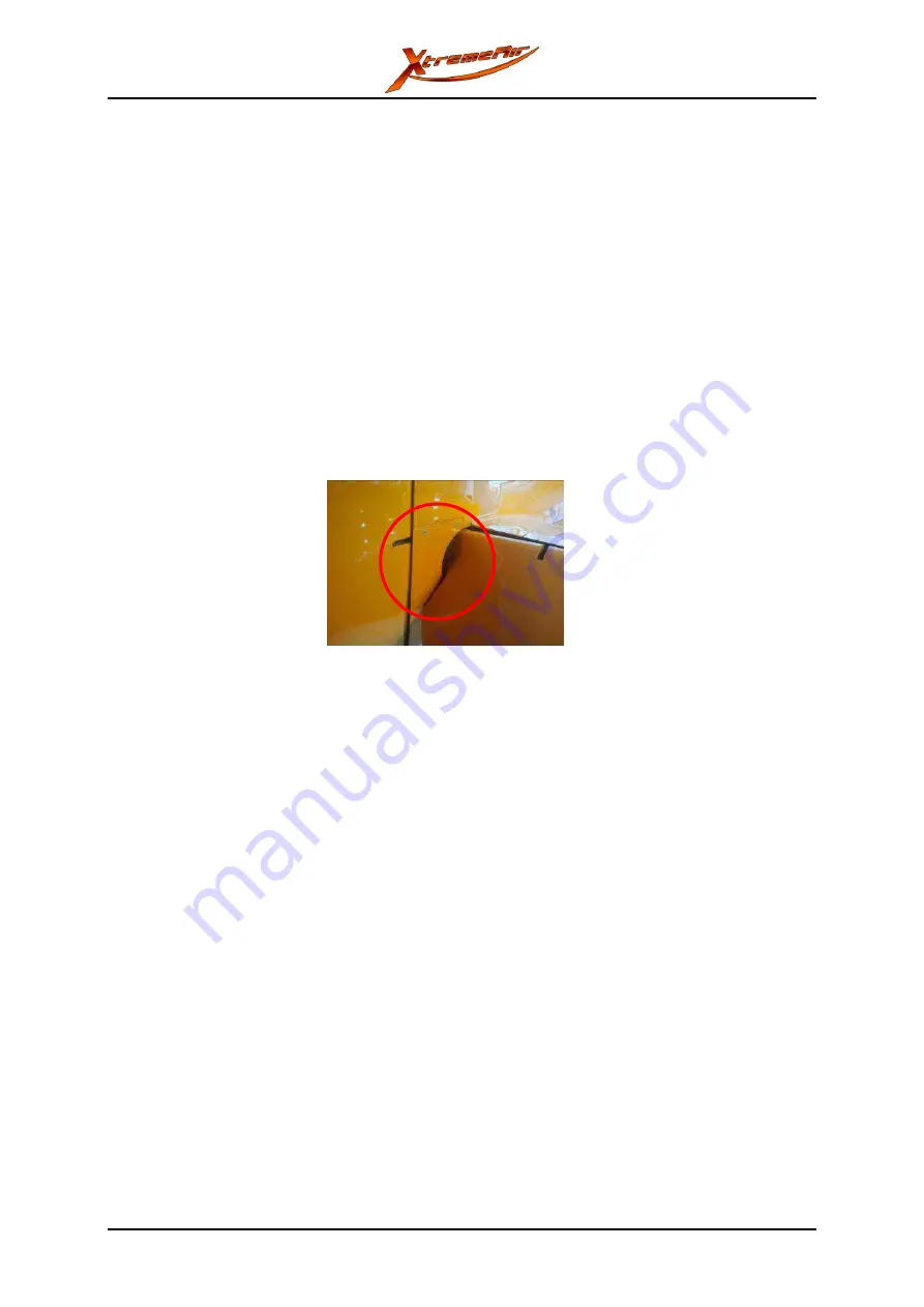
Remove the slot fairings from the vertical tail. (8x MS24693C273 screws with PH2
screwdriver). Refer to Figure 55-4.
3
Disconnect the trim tab rod. Refer to chapter 27-30-01.
4
Disconnect the elevator rod CFRP. Refer to chapter 27-30-03.
5
Remove the elevator hinge pin (5mm Allen key). Refer to Figure 55-5.
6
Remove the elevator.
Figure 55-4: Slot fairing installation
To install the elevator:
1
Install the horizontal stabilizer. Refer to chapter 55-10-00.
2
Lift the elevator into position.
3
Push the elevator hinge pin in. Refer to Figure 55-5.
4
Torque the hinge pin (5mm Allen key) to 15 Nm (11 lbs/ft). Safety the connection
with Loctite 243.
5
Seal the connection with locking varnish.
6
Connect the elevator rod CFRP. Refer to chapter 27-30-03.
7
Connect the trim tab rod. Refer to chapter 27-30-01.
8
Install the slot fairings to the vertical fin. Refer to Figure 55-4.
9
Do these checks:
The rudder must move freely from stop to stop.
Deflection, tolerance and permitted play must agree with the table of chapter 27-00-
00.
Summary of Contents for XA41
Page 281: ...Maintenance Manual XA41 XA42 AMM XA42 0040 001 C 00 Page 18 Page date Appendix 24 09 2018 ...
Page 282: ...Maintenance Manual XA41 XA42 AMM XA42 0040 001 C 00 Page date Page 19 24 09 2018 Appendix ...
Page 283: ...Maintenance Manual XA41 XA42 AMM XA42 0040 001 C 00 Page 20 Page date Appendix 24 09 2018 ...
Page 284: ...Maintenance Manual XA41 XA42 AMM XA42 0040 001 C 00 Page date Page 21 24 09 2018 Appendix ...


