Maintenance Manual XA41/XA42
AMM-XA42-0040-001 C.00
Page date:
Page
7
25.09.2018
Chapter 05
Description
Action
Signature
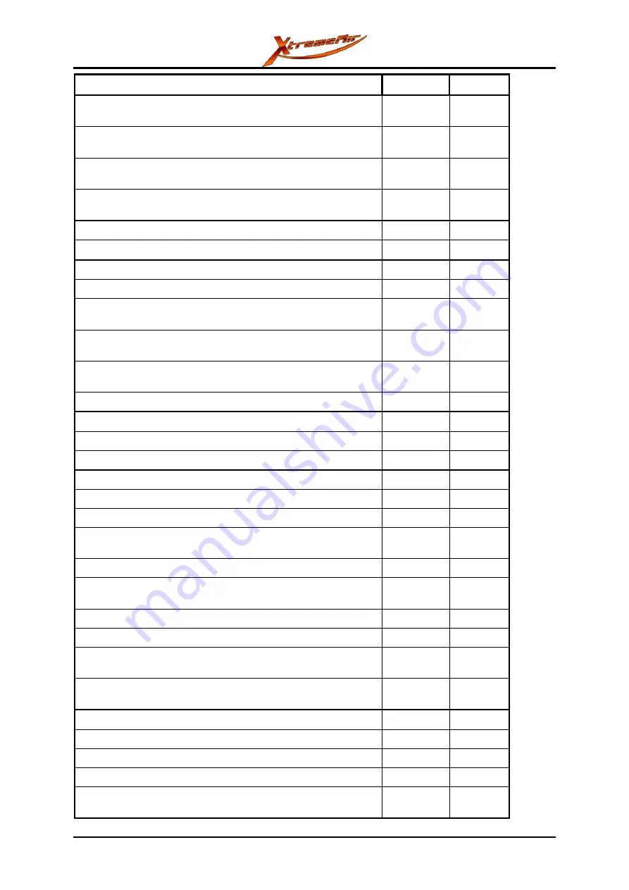
Push the trim circuit breaker in. The trim position indicator light
must come on, and the trim motor must operate correctly
CHECK
Push the GPS circuit breaker in. The GPS screen must come
on
CHECK
Push in the COM circuit breaker. Set the radio to ON and make
sure that the radio display comes on
CHECK
Push XPDR circuit breaker in. Set the transponder to ON and
make sure that the transponder display comes on
CHECK
The wiring loom has the correct routing and is safely installed
CHECK
The cables are correctly connected to the instruments
CHECK
MVP-50
Make sure that there are no system errors
CHECK
The fuel pressure indication is correct (the fuel boost pump
must be ON)
CHECK
The fuel quantity indication is correct (compare the value with
the actual quantity)
CHECK
The temperature indication (sensor) of each cylinder shows the
ambient temperature
CHECK
Set the Master Switch to
OFF
Pitot / Static System
The static ports are corrctly attached
CHECK
The pitot tube is correctly attached
CHECK
Left hand side console (XA42 rear cockpit)
The throttle slider is correctly installed and operates correctly
CHECK
The front and rear throttle linear ballbearing is free of dirt
CHECK
The throttle grip is correctly installed. The fixation screws are
correctly installed and the the grip is not loose
CHECK
The throttle cable is correctly installed and operates correctly
CHECK
The throttle friction screw is correctly installed and operates
correctly
CHECK
The trim indication is correctly installed
CHECK
The smoke switch is correctly installed and operates correctly
CHECK
The vernier control cable for the propeller is correctly installed
and operates correctly
CHECK
The vernier control cable for the mixture is correctly installed
and operates correctly
CHECK
Smoke System
The smoke pump is correctly installed
CHECK
The refill plug is correctly installed
CHECK
The inspection cover of the smoke tank is correctly installed
CHECK
The smoke oil hoses, joints and fittings have the correct routing
and are safely attached
CHECK
Summary of Contents for XA41
Page 281: ...Maintenance Manual XA41 XA42 AMM XA42 0040 001 C 00 Page 18 Page date Appendix 24 09 2018 ...
Page 282: ...Maintenance Manual XA41 XA42 AMM XA42 0040 001 C 00 Page date Page 19 24 09 2018 Appendix ...
Page 283: ...Maintenance Manual XA41 XA42 AMM XA42 0040 001 C 00 Page 20 Page date Appendix 24 09 2018 ...
Page 284: ...Maintenance Manual XA41 XA42 AMM XA42 0040 001 C 00 Page date Page 21 24 09 2018 Appendix ...


