background image

MINI TRACKED DUMPER

18

GB

TROUBLE SHOOTING

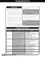
Problem

Cause

Remedy

Engine fails to 
start.

1.  Spark plug wire disconnected.
2. Out of fuel or stale fuel.
3. Choke not in open position.
4. Blocked fuel line.
5. Fouled spark plug.
6. Engine flooding.

1.   Attach  spark  plug  wire  securely  to          

spark plug.

2. Fill with clean, fresh gasoline. 
3.  Throttle must be positioned at choke 

for a cold start.

4. Clean the fuel line.
5. Clean, adjust gap, or replace.
6.  Wait a few minutes to restart, but do 

not prime.

Engine runs 
erratically.

1.  Spark plug wire loose.
2. Unit running on CHOKE.
3. Blocked fuel line or stale fuel.
4. Vent plugged.
5. Water or dirt in fuel system.
6. Dirty air cleaner.
7. Improper carburetor adjustment.

1.  Connect and tighten spark plug wire.
2. Move choke lever to OFF.
3. Clean fuel line. Fill tank with clean, 
    fresh gasoline.
4. Clear vent.
5. Drain fuel tank. Refill with fresh fuel.
6. Clean or replace air cleaner.
7. Refer to Engine Manual.

Engine 
overheats.

1.  Engine oil level low.
2. Dirty air cleaner.
3. Air flow restricted.
4. Carburetor not adjusted properly.

1.  Fill crankcase with proper oil.
2. Clean air cleaner.
3. Remove housing and clean.
4. Refer to Engine Manual.

One of the two 
tracks is blocked.

Foreign bodies have worked their way 
between the track and the frame.

Remove the foreign body.

Machine does 
not move while 
engine is running.

1.  Gear is not properly selected.
2. Driving tracks not tight enough.

1.   Ensure  gear  lever  is  not  in-between        

two different gears.

2. Tighten driving tracks.

Inspect for any loose or damaged parts. 
Repair or replace damaged parts and 
tighten loose screws, nuts or bolts.

Store your unit on flat ground in a clean, 
dry building that has good ventilation.

STORAGE

If the mini tracked dumper will not be used for 
a period longer than 30 days, follow the steps 
below to prepare your unit for storage.

Drain the fuel tank completely. Stored fuel 
containing ethanol or MTBE can start to go 
stale in 30 days. Stale fuel has high gum 
content and can clog the carburetor and 
restrict fuel flow. 

Start the engine and allow it to run until 
it stops. This ensures no fuel is left in the 
carburetor. Run the engine until it stops. 
This helps prevent gum deposits from 
forming inside the carburetor and possible 
engine damage.

While the engine is still warm, drain the oil 
from the engine. Refill with fresh oil of the 
grade recommended in the 

Engine Manual

.

1.

2.

3.

4.

6.

5.

Do not use strong detergents or 
petroleum based cleaners when 
cleaning plastic parts. Chemicals 
can damage plastics.

Do not store the machine with fuel 
in a non-ventilated area where fuel 
fumes may reach flame, sparks, 
pilot lights or any ignition sources.

Use clean cloths to clean off the outside of 
the machine and to keep the air vents free 
of obstructions.

09715UK00M112_更新回收处理标志_未发排.indd   18

2020/6/29   16:19:05

MINI TRACKED DUMPER

19

GB

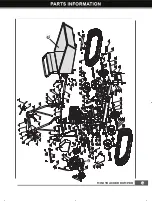
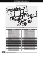
PARTS SCHEDULE

88

50

09715UK00M112_更新回收处理标志_未发排.indd   19

2020/6/29   16:19:28

Summary of Contents for 196CC/635HP

Page 1: ......

Page 2: ...is entire operator s manual before using this unit Take special care to heed the cautions and warnings The Engine manufacturer is responsible for all engine related issues with regards to performance power rating specifications warranty and service Please refer to the Engine Manufacturer s owner s operator s manual packed separately with your unit for more information Item No 09715 Engine 196cc 6 ...

Page 3: ...lames Do not touch parts that are hot from operation Serious burns may result Keep your hands clear from all rotating parts Never start or run the engine inside a closed area Do not operate on slopes with angle over 20 or tip loading at an inclined position Be aware objects may be thrown while in use The exhaust fumes are dangerous containing carbon monoxide Staying in the environment can lead to ...

Page 4: ...dental starting Be sure the engine s switch is off before transporting the machine or performing any maintenance or service Understand Your Machine Read this manual and labels affixed to the machine to understand its limitations and potential hazards Be thoroughly familiar with the controls and their proper operation Know how to stop the machine and disengage the controls quickly Make sure to read...

Page 5: ... from sparks open flames or other sources of ignition near the area of operation Never fill the fuel tank indoors To avoid sparking or arcing keep grounded conductive objects such as tools away from exposed live electrical parts and connections These events could ignite fumes or vapors Always stop the engine and allow it to cool before filling the fuel tank Never remove the cap of the fuel tank or...

Page 6: ...ur body where it would be in danger if movement should occur during assembly installation operation maintenance repair or relocation Keep all bystanders children and pets at least 23m away If you are approached stop the unit immediately Do not mount anything on the hopper and never carry passengers Never park the machine in a place with unstable ground that could give way particularly when it is f...

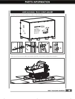
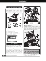
Page 7: ... UNPACKING THE CONTAINER Use the screwdriver and hammer to open all the side locks Remove all the plywood plates and remove all the loose parts on the bottom pallets 1 2 3 4 09715UK00M112_更新回收处理标志_未发排 indd 7 2020 6 29 16 18 29 ...

Page 8: ...ndlebar with the mount bracket and secure each with a spring washer flat washer and a M10x20 bolt Fasten each handlebar support onto the engine deck with a spring washer flat washer and a M8x25 hex bolt Add oil according to Engine Manual packed separately with your track dumper Engine Oil OIL HAS BEEN DRAINED FOR SHIPPING Failure to fill engine sump with oil before starting engine will result in p...

Page 9: ...ade to the trackbarrow as shown Plow Blade Optional Mount the mounting bracket to the blade using M8X30 hex bolts washers and nuts Insert the shorter control lever into the longer lever Align holes and fasten with M8X40 hex bolt washers and nut Position the pivot bracket inside the mounting bracket and align with mounting bracket holes Secure with M20X95 hex bolt washers and nut M8 X 30 X 4 a M20 ...

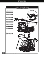
Page 10: ...Features and Controls Throttle Control Engine Switch Right Steering Lever Clutch Control Lever Left Steering Lever Hopper Track Tipping Handle Gearbox Gear Selection Lever Gas Spring Optional 09715UK00M112_更新回收处理标志_未发排 indd 10 2020 6 29 16 18 40 ...

Page 11: ...on the handles Operate the lever to turn left right Left Right Steering Lever engine will not start or run ON engine will start and run Recoil Starter Handle The recoil starter handle is used to start the engine Fuel Shut Off Valve The fuel shut off has two positions CLOSED Use this position to service transport or to store the unit OPEN Use this position to run the unit Throttle Control The throt...

Page 12: ... system components Filling to the recommended level ensures a vapor gap required to allow for fuel expansion Pay close attention while filling the fuel tank to ensure that the recommended fuel level inside the tank is not exceeded Use a portable gasoline container with an appropriately sized dispensing spout when filling the tank Do not use a funnel or other device that obstructs the view of the t...

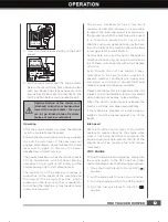
Page 13: ...iving on rough hard terrains full of sharp uneven points with a high degree of friction Even though the unit has rubber tracks remember to be careful when working in adverse weather conditions ice heavy rain and snow or on types of ground that could make the power trackbarrow unstable Please note that as this is a tracked vehicle it is subject to a considerable pitching movement when passing over ...

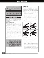
Page 14: ...e to the machine and its components Preventive Maintenance Jam Nut Adjustment Nut Adjustment Nut Jam Nut Jam Nut 1 2 3 Adjusting Steering If steering becomes difficult to engage follow these steps to adjust the cable tension Turn off the engine and disengage all command levers The engine must be cool Keep the engine s throttle lever in its SLOW position and remove the spark plug wire from the spar...

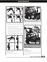
Page 15: ...t Nut 3 Jam Nut Adjustment Nut Lock Nut If the above adjustment does not create enough cable tension follow the steps below M6 20 M8 20 4 Belt Cover for Gearbox Pulley Belt Cover Drive Belt Gearbox Pulley M8 25 M8 25 5 16 30 Replacing Drive Belt Remove the belt covers as show Loosen the two bolts M8X25 and one bolt 5 16X30 that fix the two belt blockers no need to remove them Pull out the belt You...

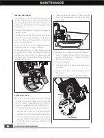
Page 16: ...urface with compact ground or on asphalt or pavement Lift the machine and set it on blocks or supports rated for the weight of the machine so that the tracks are approximately 4 off the ground Gearbox Lubrication The gearbox is pre lubricated and sealed at the factory Unless there is evidence of leakage or service has been performed on the gearbox no additional lubricate should be required until 5...

Page 17: ...the hopper and insert a support rod for safety purposes Lift the machine and set it on blocks or supports rated for the weight of the machine so that the tracks are approximately 4 off the ground Loosen the adjusting bolts and pull the steering wheel axle toward the engine then track will be loosen Steering Wheel Axle Steering Wheel Support Object Danger Area Support Rod Engine Maintenance Refer t...

Page 18: ...move while engine is running 1 Gear is not properly selected 2 Driving tracks not tight enough 1 Ensure gear lever is not in between two different gears 2 Tighten driving tracks Inspect for any loose or damaged parts Repair or replace damaged parts and tighten loose screws nuts or bolts Store your unit on flat ground in a clean dry building that has good ventilation STORAGE If the mini tracked dum...

Page 19: ...MINI TRACKED DUMPER 19 GB PARTS SCHEDULE 88 50 09715UK00M112_更新回收处理标志_未发排 indd 19 2020 6 29 16 19 28 ...

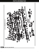
Page 20: ...MINI TRACKED DUMPER 20 GB Gearbox 50 09715UK00M112_更新回收处理标志_未发排 indd 20 2020 6 29 16 19 41 ...

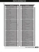
Page 21: ...Driving Wheel 2 36 Nut M8 25 37 Tensioner Pulley Bracket 1 38 Engine 1 No Description Q ty 39 Key 5x35 1 40 Belt Protect Frame 1 41 Bolt M8x30 3 42 Fixed Bracket 1 43 Washer 8 2 44 Bolt M10x60 2 45 Belt Pulley 1 46 Screw M5x12 1 47 Tensioner Pulley 1 48 Circlip 15 1 49 Bearing 6202 2RS 2 50 Gear Box 1 51 Circlip 35 1 52 Large Belt Pulley Cover 1 53 Nut M6 3 54 Bolt M6x20 1 55 Wheel Axle Press Boar...

Page 22: ... Gear 1 110 Bearing 6302 1 111 Gearshift Fork Guide Pin 1 112 Spring 1 113 Steel Ball 6 1 114 Gearshift Fork 1 No Description Q ty 115 Circlip 12 1 116 Rivet Assembly 1 117 Brake Disk 1 118 Joint Bolt 3 119 Plate 1 120 Brake Pull Plate 1 121 Washer6 4 122 Washer6 2 123 Bolt M6x16 4 124 Expansion Brake Cover 1 125 Stud 1 126 Vent Plug Bushing 1 127 Vent Plug 1 128 Screw M8X30 3 129 Expansion Brake ...

Page 23: ...Joint Bush 1 169 Intermediate Joint Bush Composite Bushing 2 170 Circlip 26 2 171 Joint Bush 2 172 Spring Gasket 4 173 Circlip 25 2 174 Washer 8 10 175 Output Shaft Bushing 2 176 Seal FB25x42x7 2 177 Output Shaft Composite Bushing 4 178 Guard Cover 1 179 Bolt M8x30 2 180 Spongy Cushion 1 181 Combined Sealing Washer 6 1 182 Combined Sealing Washer 18 2 183 Plug Screw M18x1 5 2 184 Plug 35x35 2 185 ...

Page 24: ...12 2 16 Washer12 3 17 Washer10 2 18 Washer10 2 19 Pin 10X60 1 20 Curved Support Bracket Weldment 1 No Description Q ty 21 Bolt M8X50 1 22 Active Connecting Weldment 1 23 Nut M12 2 24 Bolt M10X25 2 25 Bolt M8X35 1 26 Adjusting Rod Weldment B 1 27 Bolt M8X40 1 28 Adjusting Rod Weldment A 1 29 Handle Sleeve 28 1 30 Limiter Rod Wedment 1 31 Bolt M24X110 1 32 Limiter Weldment 1 33 Washer24 1 34 Lock Nu...

Page 25: ......

Reviews: