7
Caution
1.
This subwoofer has electronics built into the cabinet and must be properly ventilated.
2. Do not place the rear of cabinet against a wall, you must allow room for adequate ventilation
of the amplifier (at least 2 inches).
3. Do not place the subwoofer next to heat sources, such as furnace registers, radiators, etc.
4. Do not place the subwoofer near sources of excessive moisture, such as evaporative
coolers, humidifiers, etc.
5. The power cord should be routed in such a way that it will not be walked on, pinched, cut,
or compressed in any way that could result in damaging the insulation or wire. Damage to the
power cord may result in a shock or fire hazard.
Installation
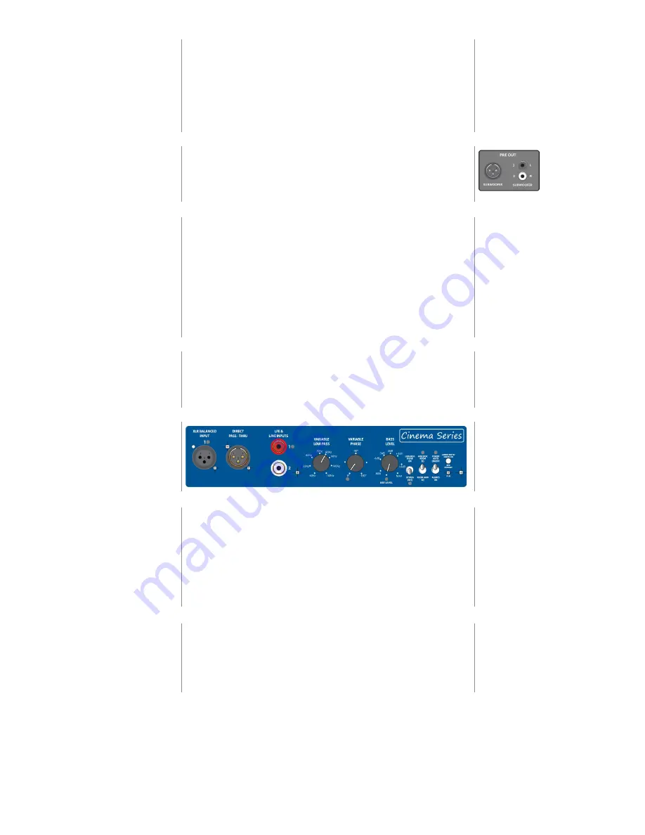
All connections for the subwoofer are located on the rear of the unit. The figure to the right illustrates
the possible connections to a typical home theater receiver or processor with preamp level subwoofer
output, both in balanced XLR and unbalanced RCA outputs. For the use with stereo equipment in music
setups the possible connections to a preamp or integrated amplifier are the same but marked either
as pre-out or audio out.
Home theater system
Utilizing this method, the receiver or processor is the main control center for the system and it provides
all the bass management (e.g. sending the low frequency signals from the satellite speaker channels
& LFE for movies, to the subwoofer), and it provides a low-pass filtered signal (bass information only) to
the subwoofer.
Most home theater receivers/processors have at least 1 unbalanced RCA “SUBWOOFER” output jack, some
models has two or even balanced XLR output/-s. For this type of equipment, connect a single high quality
cable from your receiver’s “SUBWOOFER” output jack to the subwoofer’s input marked with a grey dot.
If your receiver or processor has multiple subwoofer outputs, you may have additional connection
options. Consult the owner’s manual for your receiver/processor to verify if these outputs are all the same.
Receiver/pre-amp with
internal crossover
- Set crossover bypass switch to “BYPASS (OFF)” (indicated by grey dot)
- The “VARIABLE LOW-PASS FILTER” frequency control knob has no effect when above switch is set to
“BYPASS (OFF)”
- Adjust the “BASS LEVEL” control knob to the “REF LEVEL” (reference level) setting (indicated by grey dot)
- Set the “VARIABLE PHASE” control knob to “0” (indicated by grey dot)
Music system
Utilizing this method, the preamp provides a full range signal from both left & right audio channels to
the subwoofer. If your preamp does not offer an internal crossover or bass management functions,
the subwoofer’s built in controls will need to be properly set to utilize the built in crossover and phase
adjustments to blend the subwoofer output with the satellite speakers.
This subwoofer is designed to operate from either a full range audio signal (when using the subwoofer’s
built-in crossover) or home theater (surround sound) processor/receiver with a “SUBWOOFER” output jack
and built in low-pass filter & bass management. In both cases, proper control settings are required to
achieve optimal system performance.
Amplifier/pre-amp without
internal crossover
- Set crossover bypass switch to “LOW-PASS FILTER ON”
- Adjust the “VARIABLE LOW-PASS “ frequency control knob to blend the subwoofer output seamlessly
with your main speakers.
- Adjust the “BASS LEVEL” control knob to match the output level of the subwoofer toyour main speakers
- Adjust the “VARIABLE PHASE” control knob to smoothly blend the mid-bass output of the subwoofer to
your main speakers (refer to the section on system Calibration for further information).
Summary of Contents for Cinema Series
Page 1: ...Cinema Series Sub 1x12 OwnersManual...
Page 16: ...16...


