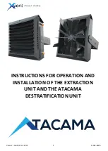
background image


Verze 1 – GBR (11.3.2020) 

D-502-0165 


INSTRUCTIONS FOR OPERATION AND 

INSTALLATION OF THE EXTRACTION 

UNIT AND THE ATACAMA 

DESTRATIFICATION UNIT


Summary of Contents for Atacama 2

Page 1: ...1 Verze 1 GBR 11 3 2020 D 502 0165 INSTRUCTIONS FOR OPERATION AND INSTALLATION OF THE EXTRACTION UNIT AND THE ATACAMA DESTRATIFICATION UNIT ...

Page 2: ...ating unit 9 3 1 1 Electrical safety before assembling the unit 9 3 1 2 Modification of existing heating distribution systems 9 3 1 3 Load bearing capacity of the assembly site 9 3 1 4 Minimum assembly distances 9 3 1 5 Minimum safety distance from flammable substances 9 3 2 Ceiling installations 10 3 3 Wall installation 10 3 4 Examples of chained heating units ATACAMA 10 3 5 Water exchanger conne...

Page 3: ...1 16 5 3 Connection of units ATA1 2 ECS ATA1 3 ECS ATA4 ECS with regulator ELEMENTAIR B M1 17 5 4 Connection of chained units ATA1 2 ECS ATA1 3 ECS ATA4 ECS with regulator ELEMENTAIR B M1 17 5 5 Connection of units withoutregulation 18 6 Commissioning 18 6 1 Before the first start check the following 18 6 2 Switching on 18 7 Regular maintenance and cleaning of Atacama heating unit 18 7 1 Regular m...

Page 4: ... facilities The unit is intended for indoor and dry spaces with ambient temperatures from 5 C to 40 C The unit can also be used for environments with a higher non condensing humidity corresponding to the protection levels IP54 and IP44 according to EN 60529 depending on the type of unit The unit may also be used in corrosion environment C2 according to EN ISO 9223 The unit must not be operated in ...

Page 5: ...t metal casing of the unit and also contains turning lamellas to direct the air blowing out of the unit as required by the user The cover is in RAL 7016 colour 2 1 2 WATER EXCHANGER Maximum permissible temperature pressure of heating medium is 120 C 1 6MPa The exchanger consists of an aluminium copper structure that is protected by powder coating RAL 9005 The connection to the water exchanger is s...

Page 6: ... 2020 D 502 0165 2 2 Main dimensions and minimum working space requirements for Atacama units ATACAMA HEATING UNIT ATACAMA D DESTRATIFICATION UNIT MIN INSTALLATION AND OPERATING SPACE MIN INSTALLATION AND OPERATING SPACE ...

Page 7: ... 0165 2 3 Technical data EC Declaration of Conformity the current and full version of the EC Declaration of Conformity can be seen on our website www xvent cz under the Atacama product documents 2 4 Technical data of water heaters ...

Page 8: ...8 Verze 1 GBR 11 3 2020 D 502 0165 ...

Page 9: ...embly site The selected assembly site must be suitable for the permanent load by the unit In case of doubt the load capacity of the wall walls must be verified by structural engineer or other responsible person 3 1 4 Minimum assembly distances the minimum distance of the unit from the wall is 0 2 m If this distance is not observed the unit may not work properly and the fan may be damaged or the un...

Page 10: ...10 Verze 1 GBR 11 3 2020 D 502 0165 3 2 Ceiling installations 3 3 Wall installation 3 4 Examples of chained heating units ATACAMA ...

Page 11: ...ing to the unit use the hexagonal profile on the water exchanger neck This prevents the exchanger outlet from being overturned which may result in irreversible damage to the water exchanger After connecting the water exchanger to the heating system a pressure test of the unit connection is recommended The tests must be carried out by a person qualified in this field with knowledge of the applicabl...

Page 12: ... to shut off the heating water supply to the exchanger when the fan is switched off Any high temperature inside the unit on the exchanger may reduce the fan lifespan 3 6 Electrical installation and electrical connection 3 6 1 General Information Safety The relevant electrical installation and electrical assembly of the units may only be performed by persons qualified for this activity with valid a...

Page 13: ...ion sleeve Table with minimum cable cross section and recommended value of safety cut out 3 6 3 Description of power and control cables The correct connection and use of all or part of the conductors taken out from the unit is subject to the selected type of control The connection of the supply and control wires must be carried out in such a way that they cannot in any case be interconnected or co...

Page 14: ... protection class according to the installation space The electric installation box must be attached to a solid non combustible surface at the maximum distance from the unit according to length of the motor cables Table of cable lengths on the unit In the wiring box connect the unit cable with cable from the mains 3 6 5 Display of electrical parameters on the unit ...

Page 15: ...ions of the control elements may only be performed by persons qualified for this activity with the applicable authorization and knowledge of the relevant standards and directives Before starting any assembly work it is necessary to switch off the power supply During installation the switch must be secured against being switched on again by an unauthorized person Before starting the installation of...

Page 16: ... 5 Atacama heating unit wiring diagram 5 1 Wiring diagram for connection of units ATA1 2 ECV ATA1 3 ECV ATA4 ECV with regulator ELEMENTAIR E M1 5 2 Connection of chained units ATA1 2 ECV ATA1 3 ECV ATA4 ECV with regulator ELEMENTAIR E M1 ...

Page 17: ...e 1 GBR 11 3 2020 D 502 0165 5 3 Connection of units ATA1 2 ECS ATA1 3 ECS ATA4 ECS with regulator ELEMENTAIR B M1 5 4 Connection of chained units ATA1 2 ECS ATA1 3 ECS ATA4 ECS with regulator ELEMENTAIR B M1 ...

Page 18: ...e assembly and installation screws tightened and the lamellas properly deflected All connections must be made in accordance with the technical documentation supplied to the unit and the documentation supplied to the control elements 6 2 Switching on After the first start check the basic functionality of the individual parts of the unit fan operation heating and also focus on the tightness of hydra...

Page 19: ...e g loose exhaust lamellas damaged fan cage o Check and replace fan filter if necessary If installed 7 2 Cleaning procedure Compressed air aggressive chemicals water or sharp objects must not be used to clean the unit Always wear protective gloves when cleaning the unit The following tools are necessary to clean the unit o Wrench of the appropriate size depending on the unit o Vacuum cleaner o A l...

Page 20: ... work must be carried out by a person with professional qualifications Complete the electrical connection precisely according to the supplied electrical documentation 8 1 Troubleshooting procedure 9 Decommissioning and recycling All unused or not operable products and packaging should be returned to the appropriate recycling locations where they will dispose of them in a professional manner Please...

Page 21: ... natural disaster When applying the warranty it is necessary to submit a report part of this document containing details of the complaining person company date and number of the sales document detail defect description wiring diagram and protection data photo of the product s manufacturing label and where appropriate serial number photo from the place of product installation product measured value...

Reviews: