


Xvent s.r.o.
Poděbradská 289
53009 Pardubice-Trnová
Verze 001-GBR (25.8.2022)
Page
3
z
6
D-502-0283
4) Electro installation – connection to the electric power network
- Before starting any installation work, make sure that the wiring box or mains power socket you want to use to connect the unit is
equipped with a protective (green-yellow) wire or contact (pin).
- If you use main plug to connect the unit, it must remain accessible at all times so that the unit can be safely disconnected from the
mains in the event of an emergency.
- The relevant current circuit must be protected by a maximum of 16 A in the electrical power distribution.
- The electrical connection of the unit to the network may only be carried out by persons qualified for this activity with a valid
authorization and knowledge of the relevant standards and directives.
- This unit belongs to the group of products with Y-type connection. If the power supply is damaged, it must be replaced by the
manufacturer, its service center or a similarly qualified person in order to avoid a hazardous situation.
- The supply voltage to the unit 1~230V/50-60Hz must not be adjusted in any way, otherwise there is a risk of unit damage.
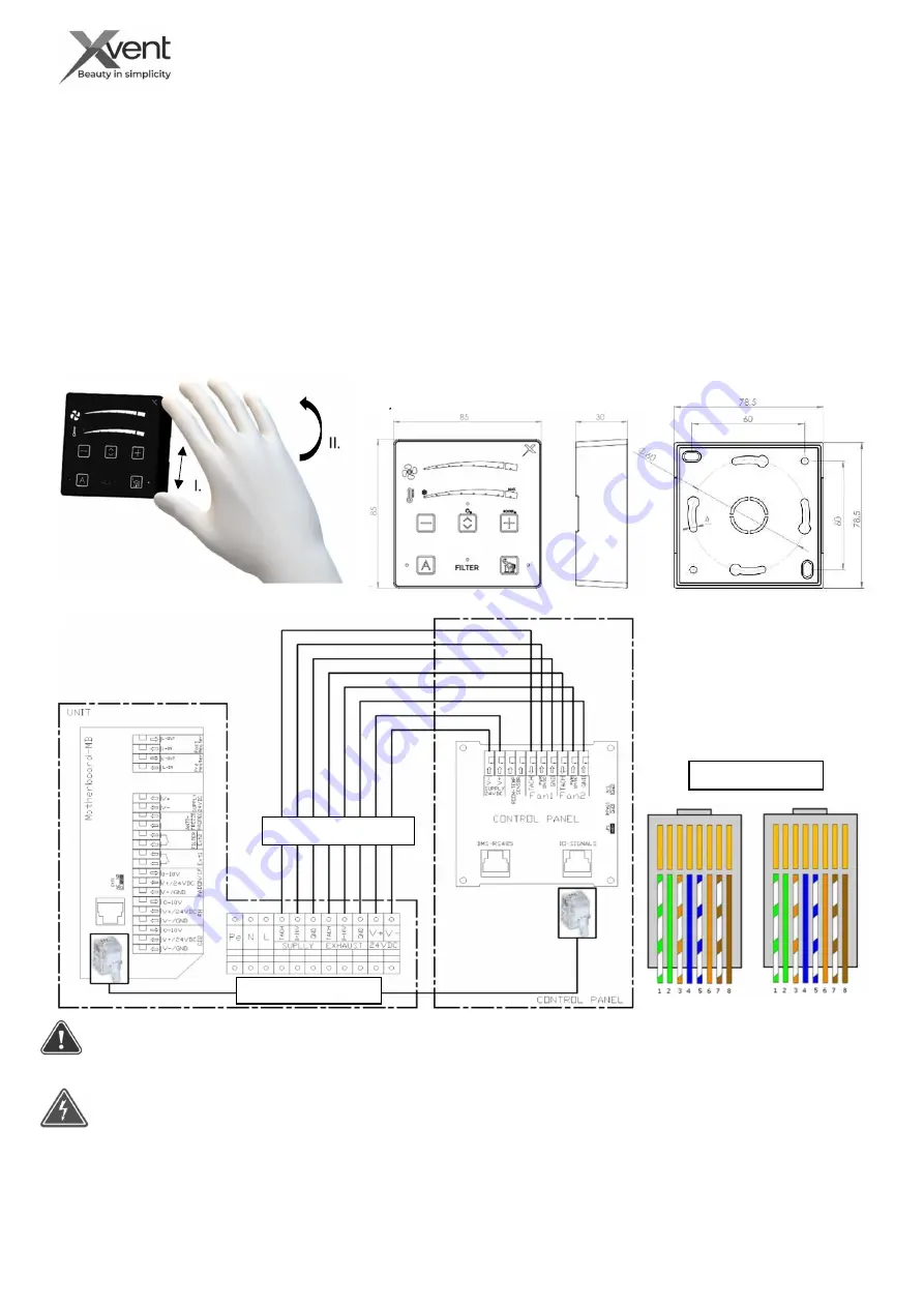
4) Installation of controls for Xflat
- The controller is connected to the regulation of the unit by connection and communication cable with a length of 3 m.
- The controller is designed to be installed on the wall in the following way:
A)
Surface-mounted installation - cables into the rail
- For installation, use electrical cable rails and an electrical
installation surface-mounted box of the appropriate size with the
possibility of connecting cables from the side.
- Open the controller – picture a)
- Disconnect all cables from controller - spring clamps with manual
wire lock are used. Proceed with care to avoid damage.
-
Install the controller box on the wiring box according to the
mounting holes.
- Drill the central hole in the back of the controller to pass the cables
-
Pull the cable through and connect according to the attached
diagram in the controller box.
B)
Concealed installation - cables in the wall
- The connection cables between the unit and the controller must be
part of the construction preparation - under the plaster. One end ends
at the installation location of the unit, the other at the location of the
controller in the flush-mounted box.
- Cables required for installation:
- 8-cores UTP cable without terminals - connection of power supply
and motor control
- 8-cores UTP cable with RJ45 8/8 terminals - communication
connection between the unit and the controller.
- Max length of connecting cables is 10m.
- Loosen the grommet nuts and unscrew the regulation cover plate
from the unit (see chapter 5.) and disconnect the connection and
communication cable according to the diagram.
a)
Open the controller
b)
Controller dimensions
c)
Connection diagram
ovladače
Connection cable
Communication cable
d)
koncovky komunikačního kabelu
Pay attention to the correct connection - observing the positions of the cables and correctly inserting the cables into the.
terminals. There is a risk of unit malfunction
-
Equip the communication cable
with terminals - RJ45 8/8 connectors
- The RJ connectors on the UTP cable
must be connected as a direct
connection (both connectors are
connected the same)
Direct connection
PRESS AND DRAG


