Xvent s.r.o.
Poděbradská 289
53009 Pardubice-Trnová
Verze 001-GBR (25.8.2022)
Page
5
z
6
D-502-0283
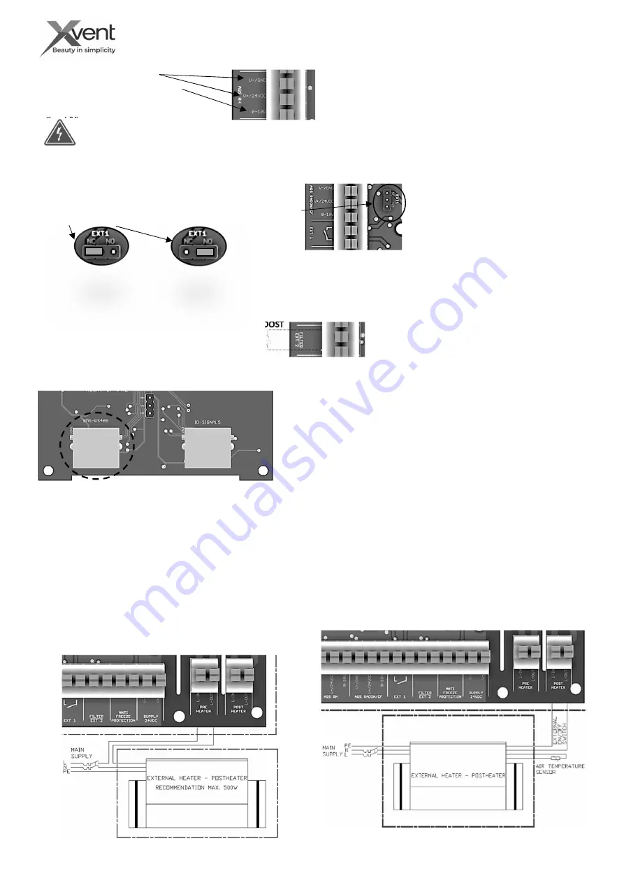
- Technical parameters of AQS sensors for connection to the unit
o
Power supply 24VDC
o
Analogue output 0- 10VDC
o
Max input 5W
o
Analogue input resistance 100kΩ
-
Functionality of the unit for connecting AQS sensors
- The unit responds with continuous control to the need for
ventilation triggered by the sensor in real time
- the switching concentration of the CO2 sensor is 800ppm, RH 65%
- cut-off concentration of the CO2 sensor is 700PPM, RH 60%
- External contact connection - EXT 1
-
The regulation of the unit allows the connection of an external contact for remote switching on and off of the unit (remote ON/OFF control).
- The external contact is designed as potential-free, it can be switched by e.g.: magnetic contact, remote switch, time relay.
- Technical parameters of the external contact EXT 1
o
Switching voltage 24 VDC / 5mA
o
The contact can change the switching logic by switching the
terminal bridge to NC or NO switching logic (factory setting).
o
-
Functionality of the unit when controlled by
an external contact EXT 2
- The external contact switches the unit on and
off (same functionality as the ON/OFF button
on the controller) with logical termination or
activation of all running processes at the time
of switching off, switching on.
The supply GND is common with the Analog input GND. If the connection is not followed, there is a risk of destroying the
control board.
- If the unit is turned on/off by an external contact, it can be turned off/on by the controller on the unit.
- Připojení externího kontaktu – EXT 2 - BOOST
- Regulace jednotky umožnuje připojení externího tlačítka (klapkový vypínač s automatickým vracením klapky – např.: zvonkové tlačítko s
vratnou pružinou) pro spuštění režimu nárazového větrání po nastavenou dobu – BOOST (dále jen BOOST) pro použití např.: v koupelně
- Technical parameters of the external contact EXT 2 - BOOST
o
Switched voltage 24 VDC / 5mA
o
The external contact is designed as potential-free
o
The factory setting is max. air output, run time 1 min
.
-
Functionality of BOOST mode – EXT 2
- An external switch turns on the BOOST mode at the set air
output and run time. After the running time of the BOOST
mode is over, the unit returns to the previous mode.
- To prematurely end the BOOST mode, hold the button for approx. 2 seconds. BOOST mode can also be turn on from the controller.
.
- Jednotku lze připojit k nadřazenému systému BMS pomocí komunikačního
protokolu modbus RTU pomocí příslušenství „XCONT-HUB“.
- Komunikační kabel připojte do ovladače do konektoru s označením BMS-
RS485, druhý konec zapojte do příslušenství „XCONT-HUB“ do konektoru
s označením BMS-RS485.
- Popis komunikačního protokolu je uveden v samostatném dokumentu
„D-502-xxx-Vxxx-xxx-MN-CENTRAL-MODBUS“.
- It is possible to connect an external electric heater with a maximum
power of 1500W, voltage 1x230V to the unit.
- The unit switches only the supply phase – potential (L-IN) to the
heater (L-OUT) in logic:
○ If the unit ventilates, the phase is switched - the potential is closed
- Connecting the unit to the superior BMS system
- Connecting an external electric postheater - POSTHEATER
○ If the unit is standing, the phase is switched - the potential is
open - the post-heating cooling function is active - 3 min
- the unit's regulation cannot detect the presence/absence of
reheating, therefore the reheating cooling function is always
active.
- It is possible to connect an external electric heater - preheating (see
accessory "XF-PH-100-03-1f") with a maximum power of 1500W, voltage
1x230V to the unit.
- Recommended heater power min 300W to 500W.
- The unit switches only the supply phase - potential (L-IN) to the heater (L-
OUT).
- The preheating switching logic is subject to the temperature on the
antifreeze sensor, which is located in the recovery exchanger in the exhaust air
branch.
o Switching temperature – 3°C (temperature on the antifreeze sensor).
o Opening temperature - 5°C – termination of anti-freeze protection –
- If the preheating is not enough, additional logics are triggered for preheating.
- Connecting an external electric preheater - PREHEATER


