25
Version 1 – GBR (25/10/2022)
D-502-0287
-
Pull the accessory and communication (modbus) cables into the unit through the prepared grommets in
the upper part of the fitting between the sockets.
-
Use the second free screw grommet to connect the communication cable for modus control of the unit.
It is recommended to pull the connector of the communication cable through the nut of the grommet
first and then through the rest of the grommet.
-
Use the membrane multi-pass for connecting the accessories. Always choose the individual
penetrations according to the size of the cable you will use to connect the accessories.
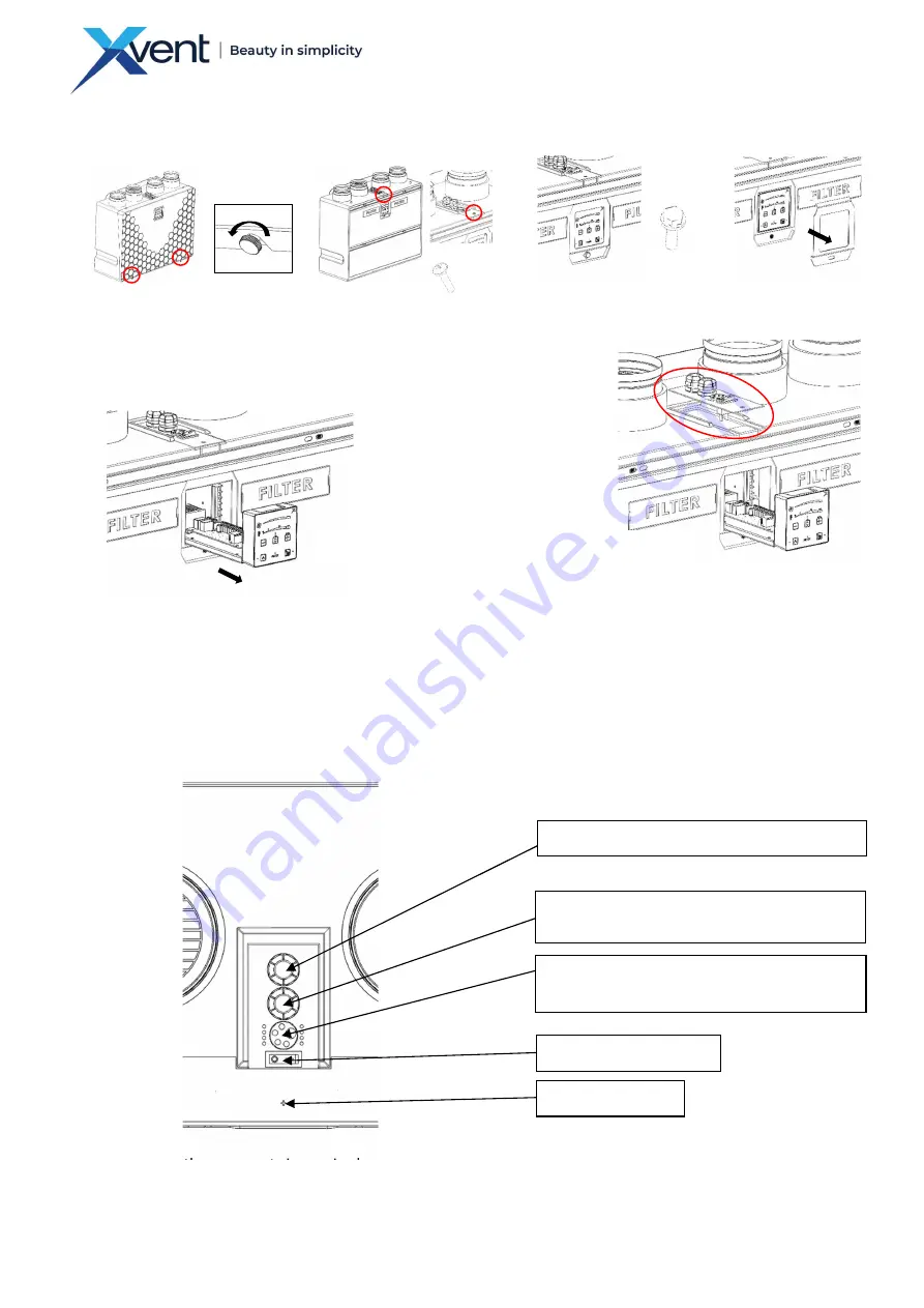
If better access to the grommets is required, proceed as follows:
o
Unscrew the locking self-tapping screw
Ø 3
.5x19
o
Loosen the grommet nut to secure the supply cable
Fig. 30
a)
Loosen the locking screws of the
design cover - remove the cover
2x
b)
Unscrew the locking screw of
the control box
1x
c)
Unscrew the 1x M6x20 screw
on the sealing plate
1x
d)
Remove the cover plate
of the control box
e)
Using the fabric strap, partially pull the control
box out of the unit body. The control box can be
pulled out only partially to allow access to the
connecting periphery.
f)
Loosen the grommet nut to
secure the supply cable
g)
Slide the grommet plate out
of the rear groove
h)
Push the grommet plate to
the side - into the longer groove
i)
Pulling upwards, tip first one
side of the sheet with the
grommets and then the other.
This will release the entire sheet
metal with grommets.
POWER SUPPLY CABLE GROMMET
COMMUNICATION
CABLE
GROMMET
(MODBUS)
MULTI-GROMMET - AIR QUALITY SENSORS
AND REHEAT CONNECTION
MAIN POWER SWITCH
LOCKING SCREW
Fig. 28
Fig. 29
Fig. 24
Fig. 25
Fig. 26
Fig. 27


