DVR User’s Manual
9
Connecting Short-term Device
If any short-term devices shall be installed to the DVR as parts of the unit
system, such as USB ThumbDrive
®
or any USB devices, etc., make sure
those devices are connected only after the unit is powered on. The reason is
because the DVR can recognize the external devices only after the power-on
process is done completely.
2.4
Rear Panel Connectors
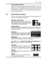
There are various connectors on the rear panel for the DVR installations. The
connectors are described as the followings.
Main Monitor (S-Video / BNC)
Both S-Video and BNC output connectors are
offered for connection to a main monitor. The main
monitor displays live image and playback recorded
video in full-screen or split-window format.
Call Monitor (BNC)
The call monitor is used to display full screen video of all installed cameras
in sequence. The BNC call monitor connector allows user to connect the
DVR with a call monitor.
VGA Output
VGA output connectors are offered for connecting
to VGA main monitors. Some models provide
one
while other models provide
two
VGA connectors.
Digital Output
Dual VGA
VGA +
Digital Output
A digital output connector is provided for connection to a displaying device
that transfers data digitally to show the best video quality.
NOTE:
Refer to
Appendix E: Simultaneous Output Options
for
detailed information about monitor functionality.
Video Input
A group of BNC connectors is offered for video
input streams from installed cameras. The number
of connectors is equal to the number of channels.
Video Out
Plenty of BNC connectors are positioned on the rear panel for looping out
the video input.
RS-232C
The unit provides a RS-232C communication port
for sending and receiving signals.
Summary of Contents for XPR8/16P
Page 2: ...DVR User s Manual 1...


