background image

Summary of Contents for XY500UTV

Page 1: ......

Page 2: ...Service Manual XY500UTV XY500LUTV XY500UE XY500UEL 4 4 ZHEJIANG XINYANG INDUSTRY CO LTD ...

Page 3: ...tains an introductory description of procedures for inspection maintenance overhaul disassembly assembly removal and installation of components and parts troubleshooting and service data together with illustrations of our UTV Model XY500 and XY500L CONTENTS Vehicle Service Information 1 Vehicle Body Muffler 2 Inspection Adjustment 3 Cooling Lubricating System 4 Removal and Installation of Engine T...

Page 4: ...ety Proper service and maintenance are essential to the customer is safety and the reliability of the vehicle Any error or oversight while servicing a vehicle can result in faulty operation damage to the vehicle or injury to others For Your Safety Because this manual is intended for the professional service technician we do not provide warnings about many basic shop safety practices e g Hot parts ...

Page 5: ...l help eliminate several potential hazards Carbon monoxide poisoning from engine exhaust Be sure there is adequate ventilation whenever you run the engine Burns from hot parts or coolant Let the engine and exhaust system cool before working in those areas Injury from moving parts If the instruction tells you to run the engine be sure your hands fingers and clothing are out of the way Gasoline vapo...

Page 6: ... parts from your dealer or for reference in case the vehicle is stolen Vehicle Identification Number 500UTV LCXRSTS1 Vehicle Identification Number 500LUTV LCXLSTS1 Vehicle Identification Number 500UE LCXRSTS3 Vehicle Identification Number 500UEL LCXLSTS3 Engine Number CF188 Engine Number EFI CF188 B NOTE The vehicle identification number is used to identify your machine 1 ...

Page 7: ... 300Kg Front 25 8 12 Tire Rear 25 10 12 Minimum turning radius 4200mm 4900mm Starting Electrical starting Form Single cylinder four stroke liquid cooling 4 valves OHC Combustion Chamber Type Triangle Valve Driving Type SOHC Chain Drive Bore stroke 87 5 82 0 mm 3 4 3 2 in Compression ratio 10 2 1 Lubrication Type Pressure and splash lubricating type Lowest fuel consuming rate g Kw h 340g Kw h Idlin...

Page 8: ...vent rust Out dimension 610 568 519 Net weight 70kg Output type Front and rear shaft output Engine Shaft running direction Clockwise from back of engine Air Filter type Sponge element filter Type CF188 B 173000 Fuel Device Valve Diameter of mixing valve 36mm Clutch Type Wet Auto Centrifugal Operation mode Automatic CVT Parking Gear shifting Gears shift Low Gear High Gear Reverse Gear Shift Mode or...

Page 9: ...asheet Lubricating device Item Standard Service limit Volume when replacing 1900ml Engine Oil Capacity Full capacity 2200ml Recommended Oil see original Specially for 4 stroke motorcycle SAE 10W 40 20W 50 Substitutes must be used in the following range API type SE or SF grade SAE type Choose from the left chart according to the environmental temperature Gap between inner and outer rotors 0 03 0 10...

Page 10: ...pening pressure of radiator cap 108kpa 1 1kgf cm2 Temperature valve open 72 2ºC Temperature valve full open 88ºC Thermostat Overall lift 3 5 4 5mm 95ºC Close Open 88 190 4F Round 88 Round Temperature of Thermostat Open Close 82 179 6F Round 82 Round Coolant Type 35 anti freeze antisepsis high boil coolant Front Rear Wheel Item Standard Service Limit Vertical 1 0mm 2 0mm Play of wheel rim Horizonta...

Page 11: ... parallel connected regulated voltage Capacity 12V36Ah Fully charged 12 8V Terminal point voltage Insufficient charge 11 8V Standard 0 9A 5 10H Battery Charging current time Quick 4A 1H Ignition system Item Standard Ignition Carburetor CDI ignition Ignition EFI ECU ignition Type DPR7EA 9 NGK Optional DR8EA D7RTC Spark Plug Spark plug gap 0 8 0 9mm Ignition timing Carburetor Max advanced angle 32 C...

Page 12: ...1 M14 1 5 97 9 Nut of driving prick gear 1 M22 1 145 10 Nut of driven prick gear 1 M16 1 5 150 11 Fixed nut of clutch 1 M18 1 5 70 Turn left 12 Nut of position limitation of driven gear 1 M60 110 Put on thread sealing glue 13 Nut of position limitation of front output bearing 1 M55 80 Put on thread sealing glue left 14 Bolts of swing arm axle 2 M14 1 25 28 15 Drain bolt 1 M12 1 5 30 16 Clutch inst...

Page 13: ...r 1 M6 12 28 Bolt on oil filter 1 M20 1 5 63 29 Bolts on start motor 2 M6 10 30 Bolts on cylinder cover 4 M10 38 2 M6 10 31 Nuts on cylinder cover 1 M8 25 32 Bolts on cylinder 4 M6 10 33 Bolt on cover of cylinder 12 M6 10 34 Bolts on chain adjuster 2 M6 10 35 Nuts on chain adjuster 1 M8 8 36 Bolts on fan motor 3 M6 10 37 Bolts on constant temperature unit 2 M6 10 38 Bolts on pump cover 3 M6 6 39 B...

Page 14: ...eering column 2 M10 25 45 50 12 Nuts on front absorber 2 M8 23 25 13 Screw of winch 4 M8 16 23 25 14 Screw of main brake pump 2 M10 60 45 50 15 Bolt on push rode of main brake 1 M10 45 50 16 Bolt on beam pin of push rode of main brake 1 M8 20 23 25 17 Nuts of flange of drive shaft 4 M14 100 18 Nuts on tyre 16 M12 55 62 19 Bolts on ceiling 4 M8 55 20 25 20 Bolts on hand brake 2 M8 20 20 25 21 Bolts...

Page 15: ... 5 12 23 25 Specification Tightening moment M6 8 12N m M8 18 25N m M10 40 50N m Other screws 8 8 grade M12 50 60N m Specification and usage quantity for fuel lubricating oil and brake liquid Category Specification Capacity Remark Fuel RQ 93or upper grade lead free gasoline 22L Content of fuel box Lubricating oil engine Gear box SAE15W 40 SF or SC 1900ml change oil 2000ml change filter 2200ml repai...

Page 16: ...1 SERVICE INFORMATION 1 13 Cables Pipes Cable Routing 1 ...

Page 17: ...1 SERVICE INFORMATION 1 14 ...

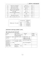
Page 18: ...1 SERVICE INFORMATION 1 15 Carburetor Condition 1 ...

Page 19: ...1 SERVICE INFORMATION 1 16 Carburetor Condition EFI Condition ...

Page 20: ...1 SERVICE INFORMATION 1 17 Carburetor Condition 1 ...

Page 21: ...1 SERVICE INFORMATION 1 18 ...

Page 22: ...re smoke and fire are strictly forbidden in the work place Special attention should also be paid to sparks Gasoline may also be explosive when it is vaporized so operation should be done in a well ventilated place Remove and Install muffler after it is fully cold This chapter is on the disassembly and installation of rack visible parts exhaust pipe Muffler and fuel tank Hoses cables and wiring sho...

Page 23: ... Installation Steering wheel Remove Exert upward to separate center cover steering wheel Remove steering wheel Installation Note Align the front wheel first and then ad just steering wheel Reverse the removal procedure for Installation Decorate cover steering stem Remove Remove bolt 2 Remove decorate cover steering stem Installation Reverse the removal procedure for Installation ...

Page 24: ...FLER 2 3 Holder meter Remove Remove eight bolts 1 Loosen all electronic component and plugs in holder meter Remove holder meter Engine cover Remove Remove four bolts 1 Remove two bolt 3 Loose cables on the engine cover 2 ...

Page 25: ...FFLER 2 4 Remove two bolts 4 Remove two nuts 4 Remove panel engine cover L Remove two bolts 4 Remove two nuts 4 Remove panel engine cover R Remove engine cover Installation Reverse the removal procedure for installation ...

Page 26: ...procedure for Installation Front side support RH Remove Remove mount bolts 3 Remove front side support RH Installation Reverse the removal procedure for Installation Front vent cover Remove Remove front side support RH LH 2 5 Remove nut 1 from front cover Remove front vent cover Installation Reverse the removal procedure for Installation 2 ...

Page 27: ...cedure for installation Seat passenger Remove Use the latch puller to unlock the seat lock Remove eight bolts 2 Remove seat passenger Installation Reverse the removal procedure for installation Seat passenger 500L Remove Use the latch puller to unlock the seat lock Remove eight bolts 3 Remove seat passenger Installation Reverse the removal procedure for installation ...

Page 28: ...e for Installation Note Check the return flexibility of gear limit and the flexibility of gear shifting Decorate cover gearshift Remove Remove bolt 2 Remove decorate cover gearshift Installation Reverse the removal procedure for Installation Gearshift unit Remove Remove bolt 4 Remove bolt 3 Loosen nut 3 Remove gearshift unit 2 ...

Page 29: ... 5 Remove handle parking brake Skid plate L Remove Remove fuel tank cap Remove bolt 1 Remove bolt 2 Remove skid plate L Installation Reverse the removal procedure for installation Skid plate R Remove Remove bolt 3 Remove bolt 4 Remove skid plate R Installation Reverse the removal procedure for Installation ...

Page 30: ...on Reverse the removal procedure for installation Rear fender R Remove Remove screw 2 Remove rear fender R Installation Reverse the removal procedure for Installation Fender cargo box L Remove Remove screw 3 Remove fender cargo box L Installation Reverse the removal procedure for Installation 2 ...

Page 31: ...rgo box R Remove Remove screw 1 Remove fender cargo box R Installation Reverse the removal procedure for Installation Cargo box Remove Remove nut 1 Remove bolt 2 Remove cargo box Installation Reverse the removal procedure for Installation ...

Page 32: ...Side door LH Remove Remove bolt 1 Remove side door LH Installation Reverse the removal procedure for installation Side door RH Remove Remove bolt 2 Remove side door RH Installation Reverse the removal procedure for Installation 2 ...

Page 33: ... 1 Remove bumper Installation Reverse the removal procedure for installation Fuel tank Remove Remove skid plate L 2 8 Loosen fuel pipe Loosen fuel sensor connector Remove bolt 2 Remove fuel tank Installation Reverse the removal procedure for installation ...

Page 34: ...se the removal procedure for Installation Headrest passenger Remove Remove nut 2 Remove headrest passenger Installation Reverse the removal procedure for Installation Backrest passenger 500L 500UEL Remove Remove bolt 1 Remove backrest passenger Installation Reverse the removal procedure for Installation 2 ...

Page 35: ...Reverse the removal procedure for Installation Safety belt passenger Remove Remove bolt 3 Remove bolt 4 Remove safety belt passenger Installation Reverse the removal procedure for Installation Safety belt fastener Remove Remove bolt 5 Remove safety belt fastener Installation Reverse the removal procedure for installation ...

Page 36: ...UTV 500UE Remove Remove bolt 1 Remove bolt 2 Loosen nut 11 Remove bolt 5 Remove roll over bar Installation Reverse the removal procedure for Installation Rear mirror LH Remove Remove rear mirror L 48 Rear mirror RH Remove Remove rear mirror R 49 2 ...

Page 37: ...bar 500LUTV 500UEL Remove Remove bolt 1 Remove bolt 2 Remove bolt 3 Remove roll over bar Installation Reverse the removal procedure for Installation Rear mirror LH Remove Remove rear mirror L 48 Rear mirror RH Remove Remove rear mirror R 49 ...

Page 38: ...ut 14 Remove bumper protector 1 Installation Reverse the removal procedure for Installation Winch cable and motor Remove Remove nut 5 and bolt 4 Remove bolt 2 and nut 5 Remove winch cable and motor 13 Installation Reverse the removal procedure for installation 2 ...

Page 39: ...r side support R Remove bolt 3 and bolt 4 Remove Remove protector R cargo box 7 Remove nut 3 Installation Remove rear side support 8 Reverse the removal procedure for Installation installation Reverse the removal procedure for Bracket cargo box installation Remove Protector L dump box Remove nut driver 30 Remove Remove bracket cargo box 21 Remove bolt 3 and bolt 4 Installation Remove protector L c...

Page 40: ... the muffler is cooled down Remove Remove connect nut 1 on muffler pipe elbow Remove bolt 1 Remove exhaust pipe protector F Caution Perform disassembly only after the muffler is cooled down Remove bolt 2 Remove muffler Note Replace sealing gasket when installing the muffler 2 ...

Page 41: ...2 VEHICLE BODY MUFFLER 2 20 Description of visible parts ...

Page 42: ...mful components like CO etc in the exhaust gas The muffler and engine are still very hot when the engine is just stopped Careless contact may cause serious burn Be sure to wear fatigue dress with long sleeves and gloves if the work has to be done after the engine is just stopped Gasoline is highly flammable smoking is strictly forbidden in the work place Keep alert on the electrical sparks Besides...

Page 43: ... vehicles that are used in severe conditions Km Initial 250km Every 500 km Every 1000 km Interval Item Hours Initial 20 hours Every 50 hours Every 100 hours Remarks Valve clearance I I IN 0 05 0 10 EX 0 17 0 22 Idle Speed I I 1300 100r min 1400 100r min EFI I I Spark plug R Every 6000km No carbon deposit Gap 0 8 0 9mm Air Filter I C R every 20000km Fuel Hose carburetor I Clutch I R every 4 year Dr...

Page 44: ......

Page 45: ...ard Looseness of joint parts Drive Train Final shaft Drive shaft Sway of Spline Spark plug Ignition Device Ignition timing Battery Terminal Joint Electrical System Wiring Looseness and damage of joints Fuel leakage Fuel device Throttle Coolant level Engine Cooling system Coolant leakage ...

Page 46: ...ction Alarm and lock device Function Instruments Function Looseness or damage caused by improper installation Exhaust pipe and muffler Function of muffler Frame Looseness and or damage Others Lubrication grease of frame parts Abnormal parts which can be determined when driving Make sure if there is any abnormal with relative parts 3 ...

Page 47: ...ccordingly In case of sway of the steering stem tighten the locknut or disassemble the steering stem for further check Park the vehicle on level place slowly turn the steering wheel left and right to see if it can turn freely In case there is any hindrance check if there is any interference If no check the steering tie rod end and check if the steering stem bearing is damaged Note Make sure the st...

Page 48: ...s Keep the fluid away from these parts Slightly turn the steering wheel left and right till the master cylinder is in horizontal then remove the fluid reservoir cap Brake Disc Brake Pad Wear of brake pad Check the brake pad wears from the mark as indicated Replace the brake pad if the wear has reached position of wear limit trough Note The brake pad must be replaced with a whole set Checking and r...

Page 49: ...heel is tightened and check whether it sways Not tighten enough Tighten it sway Replace the rocker arm Front Toe in size Park the vehicle on level place measure the front toe in Toe in B A 0 10mm Toe in out of the range Adjust the locknut of tie rod Note After the toe in has been adjusted slowly run the vehicle to check whether the direction of vehicle can be controlled by steering wheel ...

Page 50: ...ll reduce the comfort of operation and riding and may cause deflected wear of the tires Specified pressure tire Front wheel Rear wheel Pressure 145kPa 21 1PSI 193kPa 28 1PSI 25 8 12 25 10 12 Tires sizes 205 80 12 255 65 12 Tire Tread Check the tire tread Tread Height if 3mm then Replace with new tires Note When the tread height is less than 3mm the tire should be replaced immediately 3 ...

Page 51: ...f Wheel Bearing Lift the front wheel Make sure there is loading on the vehicle shake the wheel in axial direction for any sway In case of any sway disassemble the front wheel and check the bearing Suspension System Park the vehicle on lever place press the vehicle Several times up and down as illustrated on the right In case of any rocking or abnormal noise check whether there is any oil leakage f...

Page 52: ... the gear to check for flexibility and gear engagement Adjust the gearshift rod if necessary Release the lock nut to adjust the length of gearshift rod Carburetor Fuel Device Status of the fuel system Remove the seat 2 6 Check the fuel hose for any aging or damage Aged or damaged fuel hose Replace Check if there is cracks or bending with the vacuum tube Cracked or bended vacuum tube Replace EFI 3 ...

Page 53: ...n adjust Loosen locknut of throttle cable turn the regulator and adjust free play of throttle pedal After adjusting tighten locknuts and install throttle cable sleeve Replace with a new throttle cable if the specified free play could not be acquired by adjusting the regulator or if there is still stickiness with the throttle ...

Page 54: ...tion hole on left crankcase Insert feeler gauge to check the clearance between the valve stem end and the adjust bolt on the rocker arm If the clearance is incorrect bring it into the specified range using the special tool Inspect initially at 20 hour break in and every 40 hours or every 1000km thereafter Inspect the clearance after removing cylinder head Valve Clearance When cold IN 0 05 0 10mm E...

Page 55: ...for several minutes measure engine speed with a tachometer Set the engine idle speed between 1200 1400 r min by turning the throttle stop screw of carburetor Engine idle speed 1300r min 100r min Tool Tachometer SPARK PLUG Remove the spark plug with a special tool Specification DER7EA 9 NGK If the electrode is extremely worn or burnt or spark plug Caution Securely tighten the locknut after completi...

Page 56: ... with a non flammable cleaning solvent A Immerse the filter element in cleaning solvent and wash it Press the filter element between the palms of both hands to remove the excess solvent Do not twist or wring the element or it will tear Immerse the element in engine oil B and then squeeze out the excess oil leaving the element slightly wet Caution Check the thread size and reach when replacing the ...

Page 57: ...cial Tool Rotor Holder Remove primary sliding sheave 1 Hold the secondary sheave with special tool and loosen secondary sheave nut Remove secondary sheave together with drive belt Special Tool Rotor Holder Remove drive belt from secondary sheave Warning Never use with gasoline or low flash point solvents to clean the filter element Note If driving under dusty conditions clean the air filter elemen...

Page 58: ...g sheave and primary fixed sheave Hold secondary sheave with a special tool and tighten the nut to the specified torque Nut Secondary Sheave 115 N m Install primary sheave and nut Hold the primary sheave with a special tool and tighten the nut to the specified torque Nut Primary Sheave 115N m Turn primary sheave until the drive belt is properly seated and both the primary and secondary sheaves rot...

Page 59: ...or SG Replacing Engine Oil Remove left side cover 1 oil dip rod 2 drain bolt 3 and washer 4 Drain out the engine oil while the engine is still warm Clean oil dip rod drain bolt and washer with solvent Install washer and drain bolt Drain Bolt 30 N m Fill engine oil about 1900ml Install oil dip rod start the engine and allow it to run for several minutes at idling speed Turn off the engine and wait ...

Page 60: ...gine oil about 2000ml and check see Replacing Engine Oil Tool Oil Filter Wrench Inspection of External Oil Pipe Check external oil pipe for leakage or damage Leakage or Damage Replace Caution The engine oil should be changed when the engine is warm If the oil filter should be replaced replace engine oil at the same time Engine Oil Capacity When replacing oil 1 9L When replacing oil filer 2 0 L Eng...

Page 61: ... bolt Install radiator cap securely after filling coolant Start the engine and keep it running for several minutes After warm up and cooling down the engine open radiator cap and check coolant Fill the specified coolant until the level is between the upper and lower lines on the reservoir tank Fill coolant into the reservoir tank till between upper an lower limit Check initially at 40 hours or 100...

Page 62: ...ting Cylinder Pressure Warm up the engine before testing Make sure battery is fully charged Remove spark plug 1 Install cylinder pressure gauge 2 in spark plug hole and tighten nut Keep throttle full open Press start button crank the engine a few seconds Record the maximum reading of cylinder pressure Tools Cylinder Pressure Gauge Adaptor Warning Never mix with other brand Perform inspection every...

Page 63: ...sage Combination of above items Testing Oil Pressure Remove bolt Connect tachometer with ignition coil Install oil pressure gauge and joint seat to main oil gallery Warm up engine as per following Summer 10 minutes at 2000r min Winter 20 minutes at 2000r min After warming up increase engine speed to 3000r min and record readings of oil pressure gauge After testing apply thread locker to the thread...

Page 64: ...ement speed is out of the above range check the following Clutch shoes Clutch shoe wheel Primary and secondary sheave Refer to Chapter 12 for inspection of clutch II Clutch Lock up Inspection Connect the tachometer to ignition coil Start the engine Shift gear lever to High position Apply front and rear brakes as firmly as possible Fully open the throttle for a brief period and note the maximum eng...

Page 65: ...ircuit 4 3 Inspection and Cleaning of Radiator and Water Hoses 4 4 Inspection of Fan Motor 4 5 Inspection of Water Temperature Sensor 4 6 Inspection of Thermostat 4 6 Water Pump 4 7 Water Pump Removal and Disassembly 4 7 Inspection 4 9 Water Pump Assembly and Installation 4 10 Lubrication System Illustration 4 14 ...

Page 66: ...4 COOLING AND LUBRICATIING SYSTEM 4 2 Cooling System Illustration 4 ...

Page 67: ...ere is leakage with the cooling system In this case check the complete system and replace the leaking parts or components Note Use high quality ethylene glycol base antifreeze and mixed with distilled water Never mix an alcohol base antifreeze and different brands of antifreeze The ratio of antifreeze should not be more than 60 or less than 50 Do not use anti leak additive Warning DO NOT open radi...

Page 68: ...re requirement replace it Radiator Cap Valve Opening Pressure Standard 108 kPa Tool Radiator Cap Tester Radiator Inspection and Cleaning Remove dirt or trash from radiator with compressed air Correct the radiator fins with a small screwdriver Radiator Hose Inspection Check radiator hoses for leakage or damage Leakage or Damage Replace Check tightening of clamps Replace the clamps if necessary Afte...

Page 69: ...oswitch Remove thermoswitch Check the thermoswitch for closing or opening by testing it at the bench as illustrated Connect the thermoswitch to the circuit tester place it in a vessel with engine oil Place the vessel above a stove Heat the oil to raise the temperature slowly and take the reading from thermometer when the thermoswitch closes and opens Tool ammeter Thermoswitch Operating Temperature...

Page 70: ...e temperature slowly and take the reading from thermometer and ohmmeter Water Temperature and Resistance Temperature 50 80 100 120 Resistance Ω 154 16 52 4 27 3 16 2 Installation Apply a little thread locker and install it to the cylinder head by tightening to the specified torque Water Temperature Sensor Tightening Torque 10N m After installation check the coolant level Fill coolant if necessary ...

Page 71: ...stat valve opens Thermostat Valve Opening Temperature 68 74 Keep heating the water to raise the water temperature Just when the water temperature reaches the specified value the thermostat valve should have been lifted by 3 5 4 5mm Installation Reverse the removal procedure for installation Apply coolant to the rubber seal of thermostat Install thermostat case Tighten to the specified torque Tight...

Page 72: ...lamps and water hoses Release bolts and remove water pump Remove O ring Remove the overflow tube Release water pump cover screws water pump cover and gasket Remove E ring and impeller Remove seal ring and rubber seal Note Do not reuse the O ring 4 ...

Page 73: ...il seal Remove bearing with special tool Note The bearing does not need to be removed if there is no abnormal noise Note Do not reuse a removed bearing Inspection of Water Pump Bearing Check the play of bearing by hand while it is still in the water pump body Turn inner race of bearing to check for abnormal noise and smooth rotation Replace the bearing if there is abnormal condition Mechanical Sea...

Page 74: ...l Water Pump Body Check the mating mace of water pump body with bearing and mechanical seal Damage Replace Impeller Check the impeller and shaft for damage Damage Replace Assembly and Installation of Water Pump Install oil seal with special tool Tool Oil Seal Installer Apply a little grease to the oil seal lip Note The stamped mark on the oil seal faces outside 4 ...

Page 75: ... Installer Note The stamped mark on the bearing faces outside Install seal ring to impeller Clean off the oil and grease from mechanical seal and install it into the impeller Apply grease to impeller shaft Install impeller shaft to water pump body Note Apply sealant to side A of mechanical seal Note A side of mechanical seal faces impeller ...

Page 76: ... Install new gasket to water pump body Install water pump cover and tighten the bolts and bleed bolt Water Pump Cover Bolts Tightening Torque 6N m Check impeller for smooth turning Install the new O ring Note Use the new O ring to prevent oil leakage Apply grease to O ring 4 ...

Page 77: ... 13 Install water pump and tighten the bolts to the specified torque Water pump bolts tightening torque 10N m Connect water hoses Add coolant Install left side cover Note Set the water pump shaft slot end B to oil pump shaft flat side A ...

Page 78: ...4 COOLING AND LUBRICATIING SYSTEM 4 14 Inspection of Lubrication System 3 18 Inspection of Oil Pump and Relief Valve 6 41 4 ...

Page 79: ...ify the frame body of Engine bolt and cable etc Please blind up the frame when removal the engine Don t removal engine from the bodywork when operating as follows OIL PUMP CARBURETOR AIR FILTER COVER CYLINDER HEAD CYLINDER HEAD CYLINDER CAMSHAFT CVT SYSTEM LEFT SIDE COVER DECELERATE BOX RIGHT SIDE COVER AC MAGNETO WATE PUMP PISTON PISTON RING PISTON PIN Separately the engine from the bodywork when...

Page 80: ... Remove carburetor Remove hoop Remove water inlet hose of engine Remove inlet and outlet oil hose of engine Remove bolt Remove shift of gearshift Remove hoop Remove water outlet hose of engine Remove magneto connector speed sensor connector trigger connector water temperature sensor connector gear position sensor and so on 5 ...

Page 81: ...NGINE TRANSMISSION SYSTEM AND GEARSHIFT 5 3 Remove spark plug Separate jacket of starter relay remove nut remove anode cable of starter relay Remove bolt and cathode cable of starter rely Remove fixing bolt of engine ...

Page 82: ...5 REMOVAL OF ENGINE TRANSMISSION SYSTEM AND GEARSHIFT 5 4 Remove hoop of air inlet and outlet duct for CVT Remove carburetor Remove air filter Remove muffler 2 18 Remove gearshift 2 7 5 ...

Page 83: ...r axle Install water inlet and out let hose in the en Disassembly gine by hoop Hang the bodywork in the air by jack keep it Install anode and cathode cable of starting doesn t falling Joint the connector of electrical cable Remove cover parts Chapter 2 Install cap of spark plug Remove front and rear wheels and rocker Install shift of gearshift Chapter 8 Chapter 9 Install air filter carburetor and ...

Page 84: ...5 REMOVAL OF ENGINE TRANSMISSION SYSTEM AND GEARSHIFT 5 6 Remove bolt and nut fixed in the frame of front axle Remove bolt and nut fixed in the frame of Rear axle 5 ...

Page 85: ...ear axle 45 50N m Bolt torque of Front and Rear drive shaft 40 45N m Gearshift Disassembly Remove seat driver 2 6 Remove seat passenger 2 6 Remove decorate cover gearshift 2 7 Remove Bolt Remove nut Remove gearshift rod Remove the 3 bolts Remove gearshift unit Installation Reverse the removal procedure for installation Make sure that gearshift is flexible Need to inspect agility of gearshift if no...

Page 86: ...7 6 60 Starting Driven Gear 6 8 6 47 6 59 Starting Dual Gear Idle Gear 6 8 6 48 6 59 Engine Left Side Oil Pump Sprocket and Chain 6 8 6 59 CVT Cover 6 9 6 51 6 58 Drive Belt 6 9 6 36 6 57 Primary Sheave Secondary Sheave 6 9 6 30 6 57 CVT Housing Clutch Outer Face 6 10 6 51 6 57 Clutch 6 10 6 28 6 56 Engine Right Side Timing Chain 6 10 6 23 6 56 Gear Position Bolt 6 11 6 56 Right Crankcase 6 11 6 5...

Page 87: ...e Pipe Remove water hose clamp and Remove water hose Remove screw and water hose Left Side Cover Remove 6 bolts M6X20 of left side cover Remove left side cover Recoil Starter Remove 4 bolts M6X12 of recoil starter Remove recoil starter Inspection Plug Remove inspection plug with screwdriver ΔEngine Front Side Spark Plug Remove spark plug with special wrench Tool Spark Plug Wrench Turn crankshaft a...

Page 88: ...head cover Remove cylinder head cover Timing Chain Tensioner Remove screw plug insert a flat screwdriver into slot of timing chain tensioner adjuster turn it clockwise to lock tensioner spring Remove tensioner fix bolt Remove tensioner and gasket Camshaft Loosen timing sprocket bolt Remove timing sprocket bolt and lock 6 ...

Page 89: ... tensioner plate Cylinder Head Remove cylinder head bolt Remove cylinder head bolts diagonally Remove cylinder head Cylinder Remove dowel pin and cylinder head gasket Remove timing chain guide Note Take care not to drop spacer bolt bolt lock and C ring into crankcase Note Take care not to drop dowel pin into crankcase ...

Page 90: ...tarting motor Note Take care not to drop dowel pin into crankcase Note When performing above removal process be sure to hook up timing chain to prevent it from falling into crankcase Note Put a clean rag under piston so as not to drop piston pin circlip into crankcase Notes When installing piston make sure its identification conforms to that of cylinder When removing piston pin clean off burrs of ...

Page 91: ...mover Sector Gear Remove bolt 1 of gearshift rocker arm Remove gasket 2 and gearshift rocker arm 3 Remove bolt of sector gear housing cover Remove wire clip and sector gear housing cover Remove dowel pin and gasket Remove drive sector gear 4 Remove bolt 5 of driven sector gear Remove washer 6 and driven sector 7 ...

Page 92: ...Drum Remove the sheave drum by using a suitable bar Remove washer and sheave drum Left Crankcase Cover Remove bolts Remove left crankcase cover Remove dowel pin and gasket Magneto Rotor Install attachment 1 to crankshaft end Install special tool to rotor thread Remove rotor and woodruff key Tool Rotor Remover 6 ...

Page 93: ...ng Motor Gear Remove driven gear 1 and needle bearing Remove spacer 2 Remove dual gear and shaft 3 Remove idle gear and shaft 4 Oil Pump Sprocket and Chain Remove drive sprocket nut 5 Remove C ring 6 Remove oil pump drive and driven sprockets and chain ...

Page 94: ...gasket and dowel pin CVT Continuously Variable Transmission Remove primary sheave nut with special tool Remove primary sliding sheave Remove secondary sheave nut with special tools Remove secondary sheave Remove drive belt Tool Sheave Holder Remove primary fixed sheave Remove bolt for air guide plate Remove air guide plate 6 ...

Page 95: ...se Remove nut 2 of CVT case Remove outer clutch face and CVT case Remove dowel pin front and rear gasket Clutch Remove one way clutch Remove clutch shoe fixing nut with special tool Remove clutch shoe Note The clutch shoe nut has left hand threads Timing Chain Remove timing chain ...

Page 96: ...case bolts Remove right crankcase bolts Separate right crankcase with special tool Tool Crankcase separator Driven Bevel Gear Front Output Shaft Remove bevel gear cover bolt Remove driven bevel gear Remove front output shaft nut Caution The Crankcase separator plate should be parallel with the end face of crankcase Crankshaft should remain in the left crankcase half 6 ...

Page 97: ... seal Bearing limit nut Remove Front Output Shaft Shift Cam Fork Shaft Remove Shift Cam Fork Shaft Drive Bevel Gear Remove left crankcase from driven bevel gear Drive Shaft Drive Shaft Remove drive shaft and driven shaft Balancer Shaft Remove balancer shaft ...

Page 98: ...6 ENGINE REMOVAL INSPECTION INSTALLATION 6 13 Crankshaft Separate crankshaft from left crankcase with Special tool Tool Crankshaft Separator Oil bump Relief Valve Remove oil bump and relief valve 6 ...

Page 99: ...emove rocker arm shaft by using M6 bolts B Cylinder Head Cover Distortion Clean off sealant from the fitting surface of cylinder head cover place cylinder head cover on a surface plate and measure distortion with a thickness gauge Cylinder head Cover Distortion Limit 0 05mm Tool Thickness Gauge Distortion out of range Replace Note Cylinder head cover and cylinder head should be replaced together R...

Page 100: ... contact surface Rocker Arm I D 000 12 018mm Tool Dial Calipers Assembly Note Intake rocker arm shaft A has oil holes Apply engine oil to rocker arms and shafts Install rocker arms and tighten rocker arm shaft to the specified torque Rocker Arm Shaft Bolt 28N m Cylinder Had Disassembly Remove intake pipe Remove water temperature sensor and thermostat cover 6 ...

Page 101: ...emove thermostat Compress the valve spring and remove valve cotter with tweezers Tools Valve Spring Compressor Tweezers Remove valve spring upper seat and valve spring Remove valve from the other side Remove valve stem seal ring and valve lower seat ...

Page 102: ...old the valve head The ring like dye impression on the valve face should be continuous without any break The width of the dye ring which is the visualized seat width should be within the following range Valve Seat Width 0 9 1 1mm Tool Valve Lapper Valve Stem and Valve Guide Lift the valve about 10mm from valve seat Check the valve stem deflection in the directions of X and Y perpendicular to each ...

Page 103: ...lustrated on the right Valve head Radial Run out out of range Replace Service Limit 0 03mm Tool Dial Gauge 1 100 Magnetic Stand V Block Valve Face Wear Check each valve face for wear or damage Replace valve with a new one if it is found to have abnormal wear Measure valve head thickness T Valve head thickness T out of range Replace Service Limit 0 5mm Tool Vernier Caliper Valve Stem End Check valv...

Page 104: ...the spring to the specified length Valve spring tension out of range Replace Service Limit IN EX 182N 210N 31 5mm Tool Spring Scale Measure valve spring incline Spring incline out of range Replace Valve Spring Incline Limit 2 5º 1 7mm Assembly of Cylinder Head Install each valve spring seat Apply moly oil to valve stem seal and fit into position Material Moly oil Insert the valves with stems coate...

Page 105: ...alves to the stem end and release compressor to allow the cotter to wedge in between seat and stem Make sure that the rounded lip of the cotter fits into the groove in the stem end Tool Valve Spring Compressor Tweezers Check the sealing effectiveness of cylinder head Dip clean solution into valve IN EX and check for any leakage of valve seat after a few minutes NOTE Knock the valve end with rubber...

Page 106: ... the thread part tighten it to the specified torque Water temperature sensor Tightening torque 10 N m Install intake pipe apply lubricant to 0 ring Camshaft Check camshaft for wear and run out of cams and journals if the engines produces abnormal noise or vibration or lacks power output Any of these symptoms could be caused by wear of camshaft 6 ...

Page 107: ... whether each journal is worn to the limit by measuring camshaft journal oil clearance with the camshaft installed Camshaft journal oil clearance Service limit 0 15mm Check according to the following steps Clean off materials from cylinder head and cover Install camshaft with plastic gauge Install cylinder head cover and tighten bolts evenly and diagonally to the specified torque Tightening torque...

Page 108: ...66mm 17 484mm Tool micrometer 0 25mm Camshaft Run out Measure the run out with a micrometer Replace camshaft is the run out is out of range Service limit 0 10mm Timing Sprocket and Chain Check timing sprocket and chain for wear or damage Replace with new parts if abnormal wear or damage is found Tensioner and Chain Guide Check contact surface of tensioner and chain guide for wear and damage Replac...

Page 109: ...with a new one Cylinder Cylinder Distortion Check the gasket face of cylinder for distortion with a straightedge and thickness gauge and take clearance readings at 7 points as illustrated If the largest reading at any of the 7 points of the straightedge is out of the range replace the cylinder Cylinder Distortion Service Limit 0 05mm Tool Straightedge Thickness Gauge Cylinder Bore Check cylinder w...

Page 110: ...ard 87 460 87 480mm Limit 87 380mm Tool Micrometer 75 100mm Calculate the piston to cylinder clearance according to the above measurement If the clearance is more than 0 15mm replace the cylinder or piston or both Piston Ring to Groove Clearance Use a thickness gauge to measure the side clearance of top t ring and 2 nd ring If the clearance exceeds the limit replace both piston and piston rings Se...

Page 111: ...ing free end gap limit Top ring 8 9mm 2 nd ring 9 5mm Piston ring end gap limit Top Ring 0 60mm 2 nd ring 0 60mm Tool Vernier caliper Thickness gauge Piston Pin and Pin Bore Use a bore gauge to measure the inner diameter of piston pin bore Use micrometer to measure outer diameter of piston pin If out of limit replace both piston and piston pin Piston pin bore limit 23 030mm Use micrometer to measu...

Page 112: ...able to check and inspection of big end Connecting Rod Deflection 3 0mm Tools Dial Gauge Magnetic stand V block Connecting Rod Big End Side Clearance Push the big end to one side and use thickness gauge to measure the other side clearance If out of limit replace with a new crankshaft Connecting Rod big end side clearance 1 0mm Tool Thickness Gauge Crankshaft Run out Support crankshaft with V block...

Page 113: ...inner clutch wheel for scratches scuffs or blue discoloration or uneven wear If any damage is found replace the clutch wheel with a new one Check oil seal lip for wear or damage Wear or Damage Replace Use special tool to remove oil seal Tool Oil seal remover Use special tool to assemble oil seal Tool Oil seal installer set Check the turning of bearing Abnormal damage Replace Assembly Apply lubrica...

Page 114: ...6 ENGINE REMOVAL INSPECTION INSTALLATION 6 29 Primary and Secondary Sheave 6 ...

Page 115: ...e Disassembly Remove spacer Remove Cam and Roller Roller Check each roller and sliding face for wear and damage Wear and damage Replace Oil Seal Check oil seal lip for wear and damage Wear and damage Replace Remove the oil seal Note rollers should be replaced as a set ...

Page 116: ...e of primary sliding and fixed sheave for installation Pay attention to the following Apply grease to inner bore and oil seal lip Material Lubricant grease Position 8 rollers on the primary sliding sheave Install 4 dampers to cam Install cam to primary sliding sheave Note Wipe off any excessive grease thoroughly Take care not to attach any lubricant grease to contact surface of drive belt Notes Wh...

Page 117: ...ve and compress it by turning in the tool handle Remove ring nut Tool Secondary sliding sheave spring compressor Slowly loosen tool handle and remove the special tool Caution Do not remove the ring nut before attaching the clutch spring compressor Note Make sure that spring end A is inserted into slot B of the tool handle Note Since a high spring force applies to the secondary sliding sheave take ...

Page 118: ...ION INSTALLATION 6 33 Remove spring Remove spring seat Remove guide pin and spacer Remove secondary sliding sheave O ring and Oil Seal Check the O ring and oil seal for wear and damage Wear and Damage Replace Remove Oil Seal 6 ...

Page 119: ...ring free length If xthe length is shorter than the service limit replace with a new one Service Limit 145 4mm Secondary Sliding and Fixed Sheave Check drive face for any abnormal condition such as stepped wear or damage Wear or damage Replace Assembly Install a new O ring Apply lubricant grease to O ring oil seal lip and guide pin groove Material lubricant grease ...

Page 120: ...plate Insert spring end into the hole Compress spring with special tool Align the secondary sheave end with spring plate hole Tool Secondary sheave spring compressor Tighten ring nut temporarily Remove the special tool from secondary sheave Note To avoid damage to the oil seal lip during assembly slide the lip with a 0 1mm steel sheet as guide 6 ...

Page 121: ...Tool Ring nut wrench Sheave Holder Drive belt Check belt for any greasy substance Check contact surface of belt for any cracks and damage Check belt width with vernier caliper Damage width out of range Replace Belt width service limit 33 5mm Tool vernier caliper Caution If belt surface is stained with grease or oil degrease the belt thoroughly ...

Page 122: ...E 1 2 SHIFT CAM 1 11 DRIVEN GEAR LOW RANGE 1 3 RIGHT CRANKCASE 1 12 SPRING SHIFT FORK 1 4 LEFT CRANKCASE 1 13 RIGHT SHIFT FORK 1 5 DRIVEN SECTOR GEAR 1 14 GUIDE BAR 1 6 SPROCKET REVERSE GEAR 1 15 DRIVEN SHAFT 1 7 CHAIN REVERSE GEAR 1 16 SPRING SHIFT FORK 1 8 DRIVEN OUTPUT GEAR 1 17 LEFT SHIFT FORK 1 9 DRIVE SECTOR GEAR 1 18 SHIFT FORKASSEMBLY 1 6 ...

Page 123: ...or any damage or over wear Damage or over wear Replace Check reverse gear chain for any damage or over wear Damage or over wear Replace Disassemble driven shaft as illustrated Check each gear surface for any damage or over wear Check bearing and collar for any wear or damage Damage or over wear Replace ...

Page 124: ...d clearance 0 10 0 30mm Service Limit 0 50mm Measure shift fork groove width with vernier caliper Standard shift fork groove width 6 05 6 15mm Measure shift fork thickness with vernier calipers Standard fork thickness 5 80 5 90mm Check shift fork and for damage or bend Damage bend Replace Install shift fork to guide bar and move left and right In case of any unsmooth moving replace with a new one ...

Page 125: ...m groove for scratches damage Scratch or damage Replace Assembly Reverse the removal procedure for assembly Pay attention to the following Use new retainers Pay attention to the direction of the retainers Fit to the side where the thrust is as illustrated Coat the gears and shafts with engine oil before assembly Note Do not reuse the retainers Do not expand of the gap end of new retainers too wide...

Page 126: ...bly oil pump as illustrated 1 Oil pump housing 2 Dowel pin 3 Oil pump shaft 4 Straight pin 5 Inner rotor oil pump 6 Outer rotor oil pump 7 Oil pump cover Check oil pump housing and cover for cracks and damage Crack or damage Replace Measure top clearance a between inner and outer rotors and side clearance b between outer rotor and oil pump housing If the clearance exceeds the limit replace with ne...

Page 127: ... bevel gear nut 3 remove the drive 2 Output driven gear 6 Drive bevel bevel gear 4 and adjust washer 5 3 Drive bevel gear nut 7 Bearing press 4 Drive bevel gear 8 Bearing Check the drive bevel gear 4 and output driven gear 2 for rust scratch wear or damage Replace if any Check if the bearing 8 turns smoothly replace with a new bearing if necessary Adjust Washer 5 if any of right crankcase drive be...

Page 128: ...bevel gear Place a clean rag under bevel gear cover Remove bearing limit nut 10 with special tool and remove bearing Check driven bevel gear 8 surface for scratches wear Scratch or wear Replace Check free turning of bearing 9 and 11 Replace with a new one if any abnormal is found Use new oil seal 16 and O ring 12 when assembling Adjust washer 13 if any of right crankcase driven bevel gear 8 or dri...

Page 129: ... bevel gear in each direction and measure the backlash If the backlash is not within the specification adjust the thickness of the driven bevel gear adjust washer Re check the backlash until the backlash is correct Bevel Gear Backlash 0 1 0 2mm Adjustment Measured Backlash Washer Thickness Adjustment 0 1mm Decrease washer thickness 0 1 0 2m Correct 0 2mm Increase washer thickness Note Proper bevel...

Page 130: ...llustration on the right for tooth contact pattern and Incorrect contact at tooth top Correct Incorrect contact at tooth bottom If tooth contact is correct Contact continue the next procedure If tooth contact is not correct and adjust the thickness of the washer of drive bevel gear Repeat above steps to check tooth contact until it is correct Adjustment Tooth Contact Washer Adjustment Contact at t...

Page 131: ...alancer Shaft Remove the parts as illustrated on the right Check each part for abnormal wear or damage Wear or damage Replace Balancer shaft gear Woodruff key Balancer shaft Balancer shaft sprocket Washer Bolt Magneto Rotor Remove starter clutch nut ...

Page 132: ...of starter clutch bolt 26N m Material Thread Locker Install the starter driven gear Make that the starter driven gear turns in the opposite direction of the arrow mark B The gear cannot turn in the direction of the arrow Check starter driven gear bearing In case of anything unusual replace the bearing Remove starter driven gear bearing with special tool Install starter driven gear bearing with spe...

Page 133: ...earing 4 for smooth turning If it is stuck replace with a new one Check oil seal 5 for damage Replace it if it s damaged Apply thread locker to the bolt when assembling Tightening torque for magneto coil bolt 10N m Apply lubrication oil to bearing 4 and lubricant grease to lip of oil seal 5 when assembling Recoil Starter Disassembly 1 Recoil starter 2 Bolt 3 Washer 4 Starter pully Inspection Check...

Page 134: ...t s not necessary to disassemble it DISASSEMBLY Remove nut 10 Remove the parts from the starter housing Inspection Check all the parts for damage Damage Replace WARNING The coil spring may quickly unwind and cause injury when the sheave drum is opened Wear proper hand and eye protection beforehand 6 ...

Page 135: ... coil spring end to the starter housing wind the coil spring clockwise Hook the other end of coil spring to hook part of sheave drum Install spring clamp friction plate and bolt Turn sheave drum three times for pretension of coil spring Install handle and handle cap Tie a knot on handle and release knot Lead the rope through the hole of the starter housing and tie a knot so that the rope would not...

Page 136: ...limitator and tighten screw after applying thread locker Tool Bearing Remover Oil Seal Remover Bearing Installer CVT Case Check bearing 5 for smooth turning In case of any abnormal remove screw 3 and bearing retainer 4 and replace with a new bearing Check oil seal 7 In case of any damage replace it Apply grease to oil seal lip and install with special tool Apply lubrication oil to bearing 5 and in...

Page 137: ...olt Clean and grease the bearings turn the inner race of bearing and check the play noise and smooth turning In case of any abnormal remove bearing with special tool and replace Check all the oil seals for over wear or damage In case of any over wear or damage remove with special tool and replace with a new oil seal Remove gear sensor 11 and check for continuity with reverse gear sensor 9 with a m...

Page 138: ...ning torque 30N m Tool Bearing Remover Bearing Installer Multimeter III Engine Assembly Reverse the engine removal procedure for installation Engine Center Oil Pump and Relief Valve Install oil pump and relief valve to left crankcase as illustrated on the right Tighten to the specified torque Oil pump bolt 10N m Relief valve bolt 10N m Caution Clean all the parts before assembly Make sure that the...

Page 139: ... Tool Conrod Installer Balancer Shaft Install balancer shaft Main Shaft Counter Shaft Install main shaft and counter shaft Note Do not hammer the conrod into crankcase with plastic mallet Use special tool to avoid affect of conrod precision Caution Balancer shaft driven gear should be aligned to the mark as illustrated ...

Page 140: ...uate engine oil to each part Drive Bevel Gear Install drive bevel gear and tighten to the specified torque Drive bevel gear tightening torque 32N m Right Crankcase Driven Bevel Gear Install driven bevel gear and tighten to the specified torque Driven bevel gear tightening torque 25N m Check bevel gear backlash Refer to 12 44 Front Output Shaft Install front output shaft to right crankcase 6 ...

Page 141: ...olt tightening torque M6 10N m M8 25N M Place the steel ball and install gear positioning bolt and tighten the bolt to the specified torque Gear positioning bolt tightening torque 18M m Engine Right Timing Chain Put on timing chain 2 Clutch Install clutch 1 and nut 2 Tighten the nut to the specified torque left thread Clutch nut tightening torque 70N m Note Apply sealant evenly in an uninterrupted...

Page 142: ...ide plate and screw Primary Sheave Secondary Sheave Drive Belt Install primary fixed sheave as illustrated on the right Install drive belt between secondary sliding fixed sheave and tap with a plastic hammer to keep the belt as low as possible Note align oil nick on spacer with oil hole on the shaft Note Tighten bolt nut diagonally Use a new gasket Note Install the drive belt with the arrow on the...

Page 143: ...y sheave nut tightening torque 115 N m Tool Rotor Holder Tighten secondary sheave nut with special tool to the specified torque Secondary sheave tightening torque 115 N m Tool Rotor Holder CVT Case Cover Install the new gasket and dowel pins Note Turn the primary fixed sheave until the belt is seated in and both primary and secondary sheaves move together smoothly without slip ...

Page 144: ... Chain Install oil pump drive sprocket Install oil pump driven sprocket Install oil pump drive chain Install oil pump sprocket bolt Install sprocket retainer with a long nose pliers Tool Long Nose Pliers Dual Gear Idle Gear Install dual gear shaft and dual gear Install dual gear dual gear and bush Starting Driven Gear Install starting driven gear 6 ...

Page 145: ...sea lip Install left crankcase cover Install bolts Recoil Starter Install recoil starter 1 Install O ring 2 Install washer 3 and bolt 4 tighten to the specified torque Recoil starter bolt tightening torque 55N m Note Degrease the tapered part of rotor and crankshaft Use nonflammable solvent to clean off the oily or greasy matter and fully dry the surfaces Note Use a new gasket Note Use a new O rin...

Page 146: ...drive sector gear 4 driven sector gear 5 driven sector gear bolt Driven sector gear tightening torque 14N m Install gearshift rocker arm Install rocker arm bolt 7and washer 8 Note Before tightening the bolts be sure to insert oil pump shaft into groove of water pump shaft Note When the shift cam is in the neutral position the mark of drive sector gear should be between the two marks of the driven ...

Page 147: ...ol Oil Filter Wrench Starting Motor Apply engine oil to new O ring Install starting motor Install bolt and tighten to the specified torque Tightening torque 10N m Engine Top Side Piston Install the piston rings in the order of oil ring ring and ring The first member to go into the oil ring groove is spacer after placing the spacer fit the two side rails Warning when installing the spacer do not ov...

Page 148: ...aps are so located Apply a light coat of moly oil to the piston pin Install piston pin into holes of piston and conrod small end Place a clean rag beneath piston and install piston pin circlip Install the dowel pins and the new cylinder gasket Note When installing the piston the IN mark on piston top is located to the intake side Note while rotating crankshaft pull the cam chain upward or the chai...

Page 149: ... cylinder head bolts diagonally to the specified torque Cylinder head bolt tightening torque Initial 25 N m Final 38 N m Tighten the cylinder head nuts to the specified torque Cylinder head nuts tightening torque M6 10 N m M8 Initial 10 N m Final 25 N m Tighten the cylinder top nuts and cylinder base to the specified torque Tightening torque 10 N m Note When installing the cylinder and cylinder he...

Page 150: ... cylinder head Engage the chain on the sprocket with the locating pin B as illustrated on the right Recheck if the position of mark A and C is correct If not reassemble until it is correct Note while rotating crankshaft pull the cam chain upward or the chain will be caught between sprocket and crankcase Note Do not rotate the magneto rotor while doing this when the sprocket is not positioned corre...

Page 151: ...p the lock washer to lock the bolts Cylinder Head Cover Clean the mating surface of cylinder head and cylinder head cover Install dowel pin to the cylinder head Apply sealant to the mating surface of the cylinder head cover Install cylinder head cover bolts tighten diagonally to the specified torque Cylinder head cover bolt tightening torque 10 N m Note When tightening the cylinder head cover bolt...

Page 152: ...urn it clockwise to lock the tensioner spring Install the chain tensioner and the new washer 1 Install the bolt 2 tighten it to the specified torque Chain tensioner bolt tightening torque 10 N m After chain tensioner is installed turn the screwdriver counter clockwise The tensioner rod will be advanced under spring force and push tensioner against chain 6 ...

Page 153: ...pection Cap Install valve inspection cap bolt Spark Plug Install spark plug with special tool and tighten to the specified torque Spark plug tightening torque 18N m Tool Spark Plug Wrench Engine Periphery Recoil Starter Install recoil starter Apply thread locker to the bolts and then tighten Valve Inspection Cap Install valve inspection cap Note To avoid damage to the cylinder head thread screw in...

Page 154: ...6 ENGINE REMOVAL INSPECTION INSTALLATION 6 69 Left Plastic Cover Install left plastic cover 6 Water Pipe and Hose Install water hose 5 Install bolt 4 Install water hose 3 Install clamp 1 and 2 6 ...

Page 155: ...stment 7 5 Carburetor Assembly 7 6 Carburetor Installation 7 7 Carburetor Parameters 7 7 High Pressure Fuel Line Disassembly Installation 7 8 Throttle Body Disassembly Installation 7 8 Fuel Injector Assy Disassembly Installation 7 9 Fuel injector Assy Removal Assembly 7 9 Idle Air control valve Disassembly Installation 7 9 ...

Page 156: ...covered by dishcloth or tape for avoiding the entry of other objects into the engine from the air intake side of the engine When the vehicle will be stored for more than one month the gasoline in the high pressure fuel line and cap of the fuel injector must be discharged Otherwise the gasoline will age and form colloidal elements which may block the nozzle of fuel injector therefore the engine can...

Page 157: ...l No Description Qty 1 Idle Adjust Shaft 1 10 Drain Screw 1 2 Vacuum Chamber Cover 1 11 Float Chamber 1 3 Spring 1 12 Float 1 4 Jet Needle Holder 1 13 Needle Valve Set 1 5 Spring 1 14 Main Jet MJ 1 6 Jet Needle Set 1 15 Needle Jet NJ 1 7 Vacuum Diaphragm 1 16 Pilot Jet PJ 1 8 Piston Valve 1 17 Starter Jet GS 1 9 Enriching Diaphragm 1 18 Pilot Air Jet PAJ 1 ...

Page 158: ... float float tang for damage Damage Replace Check valve seat needle valve O ring for damage abnormal wear or dirt Damage or wear or dirty Replace Check piston valve for scratches abnormal wear or damage Scratches wear or damage Replace Check diaphragm for tears Tears Replace Check vacuum chamber cover spring for damage or cracks Damage or cracks Replace Note Valve set needle valve should be replac...

Page 159: ... Replace Check above jets for clog Blow out the jets with compressed air Insert piston valve into carburetor body and check the free movement Check free movement of throttle valve Replace with a new one if it s stuck 3 Measurement and Adjustment Keep the carburetor in a upside down position Measure distance a from the mating surface of float chamber without gasket to the top of float Float Height ...

Page 160: ...urface Connect fuel level gauge with drain pipe Tool Fuel Level Gauge Loosen drain screw Keep fuel level gauge vertical next to the float chamber line and read the fuel level a Fuel Level 3 5 0 5mm If the fuel level is not within the specification adjust the fuel level Remove carburetor Check valve seat and needle valve If either of valve seat or needle valve is worn replace both If both are fine ...

Page 161: ...e 6 Carburetor Parameters Type MIKUNI BSR36 89 Aperture No 07G0 Throat size mm 36mm Pilot r min 1300 r min 100 r min Float height mm 10 1 Fuel level mm 3 5 0 5 Main jet MJ N102221 130 Main air jet MAJ MD13 24 35 Jet needle JN J8 5E26 Needle jet NJ 785 401011 P OM Pilot jet PJ N224103 22 5 Pilot screw PS 604 16013 1A Pilot air jet1 PAJ1 MD13 24 65 Pilot air jet2 PAJ2 N211100 165 Note Align the inst...

Page 162: ...able from throttle rotory sleeve Disassemble idel air outlet pipe on throttle valve Loosen air intake connect clamp air cleaner connect clamp and remove throttle valve body Throttle Body Installation Reverse the disassembly procedure for installation Fuel Injector Assy Disassembly Disassemble the special high pressure fuel Remove the strap and fuel injector connector Disassemble bolts and remove f...

Page 163: ...groove of fuel injector cap snap spring to the edge of fuel injector cap and press the snap spring into it Idle Air Control Valve Disassembly Disassemble idle intake pipe and idle outlet pipe Loosen the strap disassemble idle air control valve and check idle air control valve Replace it when there is abnormal noise or it doesnot work Idle Air Control Valve Installation Reverse the disassembly proc...

Page 164: ... on the wheel Avoid any damage to the wheel When removing tire use the special tire lever and rim protector Maintenance Standard Item Standard Service Limit Longitudinal 0 8mm 2 0mm Rim Vibration Lateral 0 8mm 2 0mm Remained groove 3 0mm 21 1PSI 145 6 9KPa Tire Tire pressure 28 1PSI 193 6 9 KPa Front brake Free play brake lever 0mm Tightening Torque Nut Tie rod 40 45 N m Lock nut steering stem 45 ...

Page 165: ...Deformed frame Worn tiers Shaking of wheel bearing Vibration of Front Wheel Wheel rim distorted Faulty wheel bearing Faulty tire Improper balance of wheels Improper tightening of wheel axle Wheel Cannot Turn Freely Faulty wheel bearing Front wheel axle is bended Brake drag Faulty steering structure Front Suspension is Too Soft Weakened front shock absorbers Tire pressure is too low Front Suspensio...

Page 166: ...ly turn the wheel measure the rim vibra tion with a dial gauge Service limit Axial 2 0mm Radial 2 0mm Assembly Press rim into wheel Install rim on the wheel hub Tightening Torque Bolt Wheel Hub 60 65 N m Front Wheel Hub Disassembly Remove Front wheel 8 3 Front brake caliper 8 4 Rim axle nut Brake disc and wheel hub 4 bolts from front brake disc Wheel hub Installation Reverse the removal procedure ...

Page 167: ...caliper Removal Remove Front wheel 8 3 2 bolts from arm Front caliper Inspection Check brake caliper for cracks and tightening parts for oil leakage Replace if any Installation Reverse the removal procedure for installation Tightening Torque Fixing Bolt Brake Caliper 45 50N m ...

Page 168: ... bolt brake disc 45 50N m Front Brake Master Cylinder Disassembly Remove Blot 1 Nut 1 Do not remove front brake master cylinder from vehicle unless when replacing master cylinder assembly Note Do not hang master cylinder on brake hose Do not put the master cylinder upside down to avoid possible entrance of air into brake system Keep the master cylinder in the installation position Refer to Chapter...

Page 169: ...ehicle Disassembly of front brake master cylinder 8 5 Installation Reverse the removal procedure for installation NOTE Do not put the master cylinder upside down to avoid possible entrance of air into brake system Keep the master cylinder in the installation position Refer to Chapter1 for proper routing of brake hose Check brake efficiency after installation ...

Page 170: ... on a level ground and securely support front part of the vehicle Removal Remove Front wheel 8 3 Front wheel hub 8 3 Front brake caliper 8 4 Bolt1 Nut to Bolt1 Bolt3 Nut to Bolt3 Bolt2 Nut to Bolt2 for Front Left Arm Upper Bolt2 Nut to Bolt2 for Front Left Arm Lower Nut1 Slotted nut2 Steering rod Pull out steering knuckle from constant ve locity drive shaft Remove front left suspension 8 ...

Page 171: ...embly Front Suspension Removal Note Replacing front shock absorber does not require removal of other parts Park the vehicle on a level ground and se curely support front part of the vehicle Remove Bolt 8 and Nut 16 Remove front right shock absorber Inspection Oil leakage aged oil seal damage Replace 16 NUT M12 17 BUFFER COVER 18 L FR LOWER SWING ARM 19 R FR LOWER SWING ARM 20 FR ROCKER BUTTONHEAD ...

Page 172: ... manual will only introduce the removal disassembly inspection and installation of Front Right Arm Lower Refer to Front Right Arm Lower for removal disassembly inspection and installation of other rocket arms Front Right Arm Removal Remove Front right shock absorber 8 8 Bolt 8 and Nut16 Bolt7 27 and Nut3 29 Bolt6 28 and Nut2 30 Remove wheel brake caliper and wheel hub be fore removing shock absorb...

Page 173: ...d clearance Bearing cannot turn freely or clearance out of range Replace 1 BOLT M10 1 25 30 2 WHEEL HUB 3 GRIP BRAKE 4 HOOP 5 BEARING 6 TRIFURCATE SHAFT LEFT 7 TRIFUR CATE SHAFT RIGHT 8 BOLT M12 60 9 FRONT SHOCK ABSORBER 10 BOLT M10 1 25 40 11 LOCKING NUT M8 12 SPRING WASHER 13 SPRING WASHER 14 SPRING WASHER 15 HEX FLANGE BOLT M10 1 25 30 16 NUT M12 17 BUFFER COVER 18 L FR LOWER SWING ARM 19 R FR ...

Page 174: ...ive Shaft of Front Axle only does not require removal of Front Suspension Remove Front left wheel 8 3 Front left brake caliper 8 4 Front left wheel hub 8 3 Check dust boot Damaged dust boot Replace Shake constant velocity drive shaft check the agility of rzeppa universal joint free turning of bearing and any gap between rzeppa constant velocity joint and spline Stagnated turning noise gap with spl...

Page 175: ...8 FRONT WHEEL FRONT BRAKE SUSPENSION STEERING 8 12 Steering System Front Cover Steering Stem Removal Remove cover steering stem 2 2 Combination Switch Removal Remove combination switch 2 3 ...

Page 176: ... STEERING 8 13 Rear View Mirror Removal Remove left and right rear view mirrors 2 15 Note Left rear view mirror is right threaded Turn counter clockwise for removal Note Right rear view mirror is left threaded Turn clockwise for removal 8 ...

Page 177: ...8 FRONT WHEEL FRONT BRAKE SUSPENSION STEERING 8 14 Steering Stem Removal Remove Steering wheel 2 2 cover steering stem 2 2 Combination switch 2 3 Bolt Shaft assy steering joint Steering stem ...

Page 178: ...8 FRONT WHEEL FRONT BRAKE SUSPENSION STEERING 8 15 Installation of Combination Switch Install combination switch 2 3 Insert main cable with connector of combination switch 8 ...

Page 179: ...8 FRONT WHEEL FRONT BRAKE SUSPENSION STEERING 8 16 Installation of Steering Wheel Install steering wheel 2 2 Installation of Rear View Mirror Install rear view mirror 2 15 ...

Page 180: ...RING COLUMN 4 SCREW M6 12 5 LOCKING NUT M8 6 HOLDER STEERING COLUMN 7 BOLT FLANGE M8 35 8 RUBBER CUSHION COLUMN 9 BOLT M8 25 10 SPRING WASHER 11 STEERING JOINT 12 BOLT M10 30 13 SPRING WASHER Ф10 14 GASKET Ф10 15 HOOP STEERING COLUMN IRON 16 PIN SPLIT 3 5 16 17 SOLT NUT M12 18 HOOP STEERING COLUMN LEATHER 19 STEERING ASSY 8 ...

Page 181: ...sible damage to the wheels When removing tire from rim use special tire lever and rim protector to avoid damage to the rim Overhaul standard Item Standard Limit Longitudinal 2 0mm Rim vibration Horizontal 2 0mm Remained Tire Tread 1 6mm Tire pressure front 21 1PSI 145 6 9KPa Rear wheel Tire Tire pressure rear 28 1PSI 193 6 9 KPa Rear brake Brake pedal Free Play 0mm Tightening torque Rear wheel axl...

Page 182: ...balance Improper tightening of wheel axle nut Loosened wheel nut Rear shock absorber is too soft Weak spring Oil leakage from rear shock absorber Rear shock absorber is too hard Bent rear shock absorber Tire pressure is too high Poor brake efficiency Improper brake adjustment Stained brake pad or brake disk Worn or damaged brake pad 9 ...

Page 183: ...ce if necessary Slowly turn the wheel measure the rim vibration with a dial gauge Service limit Axial 2 0mm Radial 2 0mm Installation Refer to front wheel installation 8 3 Wheel hub removal Remove rear wheel 9 3 Remove axle nut Remove wheel hub Installation Reverse the removal procedure for installation Tightening torque Rim Axle Nut 180 200N m ...

Page 184: ...ion Note Refer to Chapter 1 for brake hose routing Rear Brake Disc Remove Rear left wheel 9 3 Remove axel nut Remove wheel hub Rear brake caliper 9 4 Rear brake disc 8 3 Inspection Brake Disc Thickness 16mm Replace Installation Reverse the steps of removal for installation Note Refer to Chapter 1 for brake hose routing Parking caliper Remove rear wheel 9 3 Rear drive shaft Remove two nuts Remove p...

Page 185: ...T FLANGE M10 1 25 55 12 LOCKING NUT M10 1 25 13 REAR SHOCK ABSORBER 14 BUFFERING COLLAR 15 SPRING WASHER Ф12 16 NUT M12 17 REAR LEFT ARM LOWER 18 REAR RIGHT ARM LOWER 19 WASHER Ф12 20 NUT M10 21 STABILIZER Bar 22 NUT M14 23 SPRING WASHER 14 24 BOLT M14 50 25 JOINT BEARING 26 RUBBER GASKET 27 FLANG REAR WHEEL LEFT 28 FLANG REAR WHEEL RIGHT 29 CENTER SPACER 30 BOLT FLANGE M12 1 25 30 31 BOLT FLANGE ...

Page 186: ... right absorbers Maintenance of rear absorbers only does not require removal of rear suspension Remove the following parts for rear right shock absorber 11 Bolt 12 Nut 11 Bolt 12 Nut Remove rear right shock absorber Installation Reverse the removal procedure for installation Rear Right Arm Refer to front right Arm in Chapter 8 for the removal inspection and installation of Rear Right Arm Rear Left...

Page 187: ... Tightening Torque Table Item Qty Type Torque N m Remark Fornt axle bolt 6 M8 28 25 Screw 4 M8 20 13 Screw 1 M8 10 13 Front screw 1 M14 1 5 62 Glue Bolt 6 M10 1 25 22 45 Front axle bolt 1 M14 1 25 12 25 Bolt 1 M10 1 25 25 Bearing Retainer 1 M64 1 5 7 80 Rear axle bolt 2 M10 1 25 25 40 Rear axle bolt 4 M8 25 25 Nut 1 M12 1 25 70 Bolt 4 M8 30 25 Bearing Retainer 1 M65 1 5 10 70 Nut 1 M8 16 Rear axle...

Page 188: ...e abnormal sound a Abnormal sounds during accelerating decelerating have little to do with engine working but possibly with gear worn b Constant abnormal sounds during accelerating or decelerating might be cause by gear clearance wrongly adjusted during assembling Note Wrong assembly or adjustment of the front or rear axle will aggravate gear worn and block c Slight sounds will be noticed during l...

Page 189: ...1 20 Oil seal 18 65 9 1 5 Circlip 62 1 21 Coupler 1 6 Drive clutch cover 1 22 O seal 14 6 8 1 7 Drive clutch 1 2 23 Nut washer 1 8 Washer φ83 71 1 24 Nut washer M14 1 5 1 9 Dif gear assembly 1 25 Bolt M8 20 4 10 Washer φ61 48 2 4 26 Gear motor 1 11 Bolt M10 1 25 1 27 O seal 81 2 1 9 1 12 Washer 10 1 28 Rack 1 13 Washer 14 1 29 Pin roll 1 14 Bolt M14 1 25 1 30 Screw M8 10 1 15 Oil seal 24 38 8 2 31...

Page 190: ...ylndrical surface of front axle and oil seal lips Replace broken parts if necessary z Check drive pinion gear and differential gear inspect worn surface Replace broken if necessary z Check driven gears surface gear center differential bracket differential wearing situation on the differential gear assembly Replace parts if necessary z Check inside and outside spline washer wearing status in front ...

Page 191: ... seal bearing and drive clutch assembly 24 Use screw thread fastening glue z Front differential gear case cover assembly Note Use engine oil for oil seal or bearing assembly z Differential gear assembly M10 1 25 22 Tightening torque45Nm Note Use engine for bearing and dif ferential gear Use proper washer to make gear working freely Adjust washer thickness 0 1 0 2 0 3 0 4 0 5 1 0 ...

Page 192: ... clearance between drive pinion gear and differential gear Drive bevel gear clearance measurement Install sup port tools tightening bolts M10 1 25 60 put up dial indicator make sure 21 mm is between measuring point and support tools Turn support tools counter clock and read the data Standard 0 10 0 25 Adjust washer thickness 0 1 0 2 0 3 0 4 0 5 1 0 b Shift fork and drive clutch assembly should be ...

Page 193: ... AXLE 10 7 c Use special equipment or vehicle control circuit into two stroke position before gear motor assembly d Make sure b and c is assembled using illustrated positioning bolt before gear motor and front axle ...

Page 194: ...1 21 Drive bevel gear 1 6 Adjust washer 2 1 2 22 Inner race NA5903 1 7 Ring gear rear axle 1 23 Outer race NA5903 1 8 Adjust washer 1 1 24 Adjust gasket 1 3 9 Needle bearing55BTM6720A 1 25 Washer 14 5 21 1 5 1 10 Rear gear case 1 26 Bolt M14 1 25 12 1 11 Oil sealSD4 65 90 9 NS 2 27 O ring 19 2 5 1 12 Nut M12 1 25 1 28 Bolt M20 1 5 12 1 13 Washer12 5 30 4 1 29 HE Screw M8 45 1 14 Coupler rear axle ...

Page 195: ... turing stability rollway stell ball neddle bearing as well Replace bearing if necessary Special tools are required z Check rear axle if bearing clearance is normal turing status rollway stellball neddle bearing as well Replace bearing if necessary Special tools are required z Check worn status of drive bevel gear and ring gear rear axle Replace if necessary z Check oil seal lips o ring shape Repl...

Page 196: ...e by choosing 6 thickness c Inspect installing clearance by check ing bevel gear clearance Standard 0 1 0 2 e Keep installing point bearing clear ance 0 1 0 2 by choosing 8 thickness d Drive bevel gear clearance measure ment illustration see above Install measuring tools tightening torque M14 1 25 60 Put up dial indicator and make sure distance from indicator point tomeasuringtoolcenteris22mm Coun...

Page 197: ...10 FRONT REAR AXLE 10 11 f Adjust item 29 as illustrated and make sure its end and back clearance of drive gear is 0 3 0 6 Tighten item 31 ...

Page 198: ...NG SYSTEM COMPONENTSCOMPOSITION FUNCTION 11 12 ECU 11 12 THROTTLE ASSEMBLY 11 13 INLET PRESSURE SENSOR 11 14 INTAKE AIR TEMPERATUR SENSOR 11 15 WATER TEMPERATURE SENSOR 11 16 OXYGEN SENSOR 11 17 TRIGGER 11 18 ODOMETER SENSOR 11 19 SHIFT LEVER POSITION SENSOR 11 20 FULE OIL PUMP ASSEMBLY 11 21 OIL ATOMIZER 11 22 IDLE AIR CONTROL 11 23 IGNITION COIL 11 24 6 ELECTRICITY SPRAYING SYSTEM SELF DIAGNOSIS...

Page 199: ... INSULATION TURN MULTIMETER TO 1 10Ω MAGNETO COIL RESISTANCE 0 5 1 5Ω YEL LOW YELLOW INSULATING RESISTANCE YELLOWGROUND MAGNETOR NON LOADED PER FORMANCE START THE ENGINE LET IT GOES TO 5000Rpm USE MULTIMETER MEASURE MAGNETO STATOR COIL THREE OUTPUT LINE VOLTAGE IT THE RESULT VALUE BELLOW THE SETTING VALUE CHANGE A NEW MAGNETO ADJUST MULTIMETER TO ALTERNATING VOLT AGE GRADE MAGNETOR NON LOADED STAT...

Page 200: ...ONE DATA OUT OF THE SETTING VALUE REPLACE WITH A NEW ONE ADJUST MULTIMETER TO DIODE AFTER ENGINE RUNNING BATTERY FULL POWER IF VOLTAGE BETWEEN RED LINE GREEN LINE EXCEED 15V OR UNDER 12V REPLACE WITH A NEW ONE 11 ATTENTION WHEN MULTIMETER PROBE UNCONNECTED IF THE MULTIMETER SHOWS BELLOW 1 4V THEN REPLACE IT S BATTERY ...

Page 201: ...ARTING SYSTEM TRIGGER CIRCUIT DIAGRAM STARTING MOTOR 1 Eed Cover 2 Brush Holder 1 End Cover 2 Brusher Holder 3 Brush Spring 4 O ring 5 Brush Terminal 6 Stating Motor Cylinder 7 Washer 8 Armature 9 Washer 10 Inner Cover 11 O ring ...

Page 202: ...NEW AMATURE IF THE COMMUTATOR SURFACE DISCOLOURATION POLISH WITH SEND PAPER AND WIPE UP WITH DRY CLOTH IF OVER WEAR CUT PART OF B INSULATOR WITH BLADE KAME THE DISTANCE BETWEEN A AND B TO d d 1 5mm ARMATURE COIL USE MULTIMETER CHECKING IF IT IS INTERCOMMUNICATION BETWEEN THE TERMINALS BETWEEN TERMINALS AND ARMATURES IF THEY NOT COMMUNICATION REPLACE WITH A NEW ARMATURE OIL SEAL CHECKING IF OIL SEA...

Page 203: ...PLACE WITH A NEW ONE ADJUST MULTIMETER TO 1X10Ω START AUXILIARY RELAY COILRESISTANCE 3 5Ω START AUXILIARY RELAY FULE PUMP RELAY APPLY 12VOLTS TO THE TWO TERMINALS USE MULTIMETER MEASURE IF CONTACTS A B IS MEET ADJUST MULTIMETER TO DIODE GRADE IF THE STARTING RELAY CLICKS WHEN NON LOADED 12V VOLTAGE THE TWO CONTACTS UNCONNECTED EITHER OF THE ABOVE TWO ITEMS IS SHOWS THE RELAY IS FINE ADJUST MULTIME...

Page 204: ...ANNEL SMOOTH IF LEAKAGE RELINK LEAK SECTION SECURE THE FUEL CHANNEL NO LEAKAGE USE FUEL PRESSURE GAUGE TO MEASURE FUEL PRESSURE FULE PUMP OUTPUT PORT PRESSURE 0 3 0 01Bar CHANGE ENGINE SHIFT HAND LEVER TO NEUTRAL USE DIAGNOSTIC EQUIPMENT CHECK IF AT FAULT IF YES CLEARING OF FAULT ACCORDING TO DIAGNOSTIC TROUBLE CODE CLOSE THROTTLE TURN OFF THE IGNITION SWITCH PRESS START SWITCH 3 5 SECONDS START T...

Page 205: ...ER SENSOR OUTPUT SHAFT SPEED INFORMATION GEAR SENSOR GEAR INFORMATION INCLUDING GEAR SENSOR AND REVERSE GEAR SENSOR OXYGEN SENSOR EXCESS AIR COEFFICIENT ABOVE 1 OR LOWER THAN 1 FOUR WHEEL DEAD LOCK 4WD DEAD LOCK INFORMATION ASSISTOR SWITCH RELIEF SPEED LIMIT INFORMATION 2 ECU ELECTRONIC CONTROL UNIT IT IS THE BRAIN OF THE ENGINE MANAGEMENT SYSTEM IT ANALYZE AND PROCESS KINDS OF INFORMATIONS PROVID...

Page 206: ...TO DO FUEL PIPE PRESSURE RELIEF BEFORE DISMANTLE THE OIL PIPE PRESSURE RELIEF METHOD IS AS FOLLOWING REMOVE FUEL PUMP RELAY STARTING THE ENGINE AND LET IT IDLE UNTILL THE ENGINE DIES ITSELF FUEL PIPE S DISMANTLE AND FUEL FILTER S REPLACEMENT SHOULD BE CARRY ON BY PROFESSIONAL PERSON IN WELLVENTILATED PLACE WHEN INSPECTING THE IGNITION SYSTEM ONLY IF NECESSARY DO SPARK TEST AND SHOULD BE AS FAST AS...

Page 207: ...N READ CLEAR ELECTRONIC FUEL INJECTION SYSTEM TROUBLE CODE OBSERVE DATA STREAM COMPONENETS MOTION TESTS TOOL NAME DIGITAL MULTIMETER FUNCTION INSPECT ELECTRONIC FUEL INJECTION SYSTEM VOLTAGE CURRENT RESISTANCE ETC TOOL NAME VACUUM METER FUNCTION INSPECT INLET PIPE PRESSURE STATE ...

Page 208: ...TION INSPECT ENGINE ELECTRONIC SPARK TIMING TOOL NAME CYLINDER PRESSURE GAUGE FUNCTION CHECK CYLINDER COMPRESSION TOOL NAME FUEL PRESSURE GAUGE FUNCTION INSPECT FUEL SYSTEM PRESSURE STATE JUDGE THE FUEL SYSTEM FUEL PUMP AND FUEL PRESSURE REGULATING VALVE WORK STATE 11 ...

Page 209: ...L 4 TROUBLE LAMP 5 IGNITION SWITCH POWER 6 INTAKE AIR TEMPERATURE SENSOR SIGNAL 7 REVERSE GEAR 8 4WD DEAD LOCK SWITCH SIGNAL 9 ASSISTOR SWITCH SIGNAL 10 5VPOWER OUTPUT 11 IGNITION SWITCH POWER 12 TRIGGER SIGNALA 13 TRIGGER SIGNALB 14 OIL ATOMIZER 15 OXYGEN SENSOR HEATING 16 SUPPLEMENTARY RELAY 17 IDLE SPEED CONTROL VALVE CARBON TANK CONTROLVALVE 18 WATER TEMPERATURE SENSOR SIGNAL 19 INLET PRESSURE...

Page 210: ...AIR DAMPER POSITION SNESORTRANSMIT ANGLE SIGNAL TO ECU EACH PIN FUNTION 1 CONNECT 5V POWER 2 GROUNDING 3 OUTPUT VOLTAGE SIGNAL THE RIGHT DRAWING IS THE WIRING DIAGRAM WITH ECU IDLE SPEED LIMIT SCREW NOT ALLOWED TO BE ADJUSTMENT ENGINE IDLE SPEED COMPLETELY DEPEND UPON ELECTRONIC SPRAYING SYSTEM ADJUSTMENT DO NOT ADJUST THE IDLE SPEED SCREW 11 ...

Page 211: ...OLTAGE SIGNAL THE RIGHT DRAWING IS THE CONNECTION DRAWING FOR SENSOR ECU THE RIGHT DRAWING IS THE PERMIT FITTING LIMIT IN THIS WAY CAN ENSURE THERE IS NO CONDENSED WATER INSIDE THE SENSOR THE CONDENSED WATER CAN DESTROY SENSOR INNER PRESSURE SENSING DEVICE THE PICTURE BELOW IS THE RECIPROCAL DIAGRAM DRAWING FOR PRESSURE AND OUTPUT VOLTAGE MONITOR PRESSURE RANGE 10 115kPa ...

Page 212: ...OEFFICIENT NTC THERMISTANCE IT S RESISTANCE VALUE DECREASE WHEN THE COOLANT TEMPERATURE INCREASE BUT IT IS NOT LINEAR RELATION THE SENSOR HAVE 2 PINS AND THEY CAN BE EXCHANGED USING THE RIGHT DRAWING IS THE WIRING DIAGRAM FOR SNESOR ECU THE RIGHT DRAWING IS FOR SENSOR EMPERATURE RESISTANCE PROPERTY LIST 11 ...

Page 213: ...E HEAT CONDITION THE OTHER GROUP PROVIDE TO THE METER MONITOR WATER TEMPERATURE A AND C IN ONE GROUP THEY PROVIDE WATER TEMPERATURE TO ECU B ANDTHREADED PORTION IN ONE GROUP THEY PROVIDE WATER TEMPERATURE TO THE METER THE RIGHT DRAWING IS THE WIRING DRAWING FOR SENSOR ECU AND METER THE RIGHT DRAWING IS B END AND CRUST TEMPERATURE PROPERTY LIST SIGNAL PASS TO THE METER THE RIGHT DRAWING IS END A C ...

Page 214: ...CONTENT DEFINITE IF THE GAS AND AIR COMPLETE BURNT SO AS TO ENSURE UNIT TRIPLET CATALYTIC CONVERTER HAVE MAXIMUM CONVERSION EFFICIENCY TO EXHAUST HC CO AND NOX THE PINS FUNCTION 1 CONNECT HEATING POSITIVE SOURCE WHITE 2 CONNECT HEATING NEGATIVE SOURCE WHITE 3 OUTCOMING SIGNAL NEGATIVE POLE GRAY 4 OUTCOMING SIGNAL POSITIVE POLE BLACK THE RIGHT DRAWING IS THE WIRING DIAGRAM FOR SENSOR AND ECU THE BE...

Page 215: ...RING TRIGGER PEAK VOLTAGE VALUE CONNECT MULTIMETER AND PEAK VOLTAGE ADAPTER ACCORDING TO THE RIGHT DRAWING PROBE GREEN LEAD WIRE PROBE BLUE LEAD WIRE ADJUST MULTIMETER TO ALTERNATE V ADJUST THE GEAR TO NEUTRAL ADJUST IGNITION SWITCH TO ON PRESS ON STARTING BUTTON AND LET THE ENGINE RUNNING FOR FEW SECONDS THEN START TO MEASURE THRIIGER COIL PEAK VOLTAGE REPEATED TIMES MEASURE GET THE HIGHEST TRIGG...

Page 216: ...AVE VOLTAGE SIGNAL IN PUT POWER VOLTAGE 80 3 POWER DC12V THE RIGH IS THE WIRING DRAWING OF SENSOR AND ECU ODOMETER SENSOR TESTING GROUNDING FOOT 1 CONNECT FOOT 3 12V FIXED ONE GEAR TO ODOMETER ACCORDING TO THE RIGHT DIAGRAM DISTANCE 2 5mm ADJUST MULTIMETER TODCV ROTATE THE GEAR SLOWLY MEASURE THE VOLT AGE VALUE BETWEEN FOOT 2 AND FOOT 3 TO SEE IF IT IS VARY FROM 0V 12V IF NO CHANGES THEN THE SENSO...

Page 217: ...AR IN A CERTAIN POSITION GEAR CORRESPONDING FOOT CON DUCT TO THE ENGINE COVER OR ELSE IT NONCONDUCTION WITH THE ENGINE COVER 10 REVERSE GEAR ASSEMBLE PROVIDE GEAR REVERSEINFORMATION TO ECU AND METER THE ECU ESTRICT VEHICLE SPEED ACCORDING TO THIS INFORMATION NORMALLY A B POINT CONDUCTION DONOT CONDUCT WITH THE CASE NORMALLY C LENGTH IS 3 5mm IF C LENGTH 3mm OR IF B SLIDE BLOCK YOU HAVE TO CHANGE I...

Page 218: ...ASURING THE FUEL PRESSURE CONNECT FUEL PRESSURE GAUGE TO THE FUEL PUMP FUEL DISCHARGE PORT LOCK WITH CLAMP ENSURE THERE IS NO LEAKAGE IN CONNECT AREA LINK THE CIRCUIT ACCORDING TO THE ABOVE DIAGRAM TURN OFF THE IGNITION SWITCH AND KILL SWITCH AT THIS MOMENT THE FUEL PUMP WILL WORKING FOR 5 SECONDS WHEN IT STOP THE FUEL PRESSURE SHALL REACH THE AUTHORIZED PRESSURE OR ELSE REPLACE THEENTIRE FUEL PUM...

Page 219: ...OT TURN AFTER FIXED THE CLAMP FUNCTION OF PINS ONE SIDE OF THE PLUG MARK CONNECT FUEL PUMP RELAY OUTPUT END WITHOUT MARK SIDE CONNECT ECU PIN 14 OIL ATOMIZER RESISTANCE 12 1Ω 20 THE RIGHT IS THE WIRING DIAGRAM FOR FUEL INJECTOR AND ECU FUEL INJECTOR INSTALLATION INSTALL THE FUEL INJECTOR BY PUSHING IN HAND WHEN DISASSEMBLE AND ASSEMBLING THE FUEL INJECTOR YOU MUST REPLACE THE O RING WHEN DISMANTLI...

Page 220: ... CAUSE INCORRECT IDLE SPEED WHEN WITHOUT ELECTRICAL PULSE IDLE SPEED VALVE CLOSE FUNCTION OF PINS 1 CONNECT PIN 17 2 CONNECT OIL PUMPRELAY OUTLET END THE RIGHT IS THE WIRING DIAGRAM FOR IDLE SPEED VALVE AND ECU WHEN FIXING THE IDLE SPEED CONTROL VALVE IT CANNOT BE INSTALLED LIKE THE RIGHT DIAGRAM CONNECTOR VERTICALLY DOWNWARD TO AVOID DESTROY THE ELECTRONIC COMPONENT TO AVOID SOLID BORNE SOUND TRA...

Page 221: ...NCTION OF PINS 1 GROUNDING 2 CONNECT POWER 3 CONNECT ECU 1 POINT THE RIGHT IS THE CONNECTION CIRCUIT DIAGRAM OF IGNITION COIL AND ECU MEASURING SECONDARY IGNITION VOLTAGE CONNECT THE ENGINE ACCORDING TO THE ELEC TRONIC SPRAY ELEMENTARY DIAGRAM CONNECT THE PEAK VOLTAGE GUAGE ACCORD ING TO THE RIGHT DIAGRAM START THEENGINE AFTERSTARTS THE SECONDARY IGNITION VOLT AGE SHOULD BE 15000V IGNITION COIL PA...

Page 222: ...ULT RECORD INFORMATION IN RAM TROUBLE MEMORY THE FAULT INFORMATION STORE AS TROUBLE CODE AND DISPLAY THE FAULT IN IT S EMERGENCE SEQUENCE THE FAULT CANBE DIVIDED INTO TWO TYPES STEADY FAULT AND RANDOM FAILURE ACCORDING TO IT S EMERGENCE FREQUENCY SUCH AS CAUSED BY BRIEF WIRE TURNOFF OR BAD CONNECTION OF THE CONNECTOR THROUGH DIAGNOSTIC EQUIPMENT AND THE TROUBLE LAMP YOU CAN FIND THE TROUBLE PART Q...

Page 223: ... TOO LOW 13 P0118 ENIGNE COOLANT TEMPERATURE S ENSOR C IRCUIT VOLTAGE TOO H IGH 14 P0122 THROTTLE POSITION S ENSOR CIRCUIT VOLTAGE UNDER LIMINAL VALUE 15 P0123 THROTTLE POSITION S ENSOR CIRCUIT VOLTAGE EXCEED L IMINAL VALUE 16 P0130 OXYGEN SENSOR SIGNAL UNREASONA BLE 17 P0131 OXYGEN SENSOR SIGNAL CIRCUIT VOLTAGETOO LOW 18 P0132 OXYGEN SENSOR SIGNAL CIRCUIT VOLTAGETOO HIGH 19 P0134 OXYGEN SENSOR CI...

Page 224: ...CIRCUIT OPENING 33 P0628 OIL PUMP RELAY CONTROL CIRCUIT SHORTCIRCUIT TO GROUND 34 P0629 OIL PUMP RELAY CONTROL CIRCUIT SHORTCIRCUIT TO POWER 35 P0650 MIL LAMP DRIVING STAGE TROUBLE 36 P2177 AIR FUEL RATIO CLOSED LOOP CONTROL SELF LEARNING V ALUE EXCEED UPP ER LIMIT 37 P2178 AIR FUEL RATIO CLOSED LOOP CONTROL SELF LEARNING V ALUE UNDER LOWER LIMIT 38 P1117 IDLE AIR CONTROL TEV SHORT CIRCUIT TO GROU...

Page 225: ......

Page 226: ...of glass face and damage to bulb Pay attention to the following when replacing the bulb Do not replace the bulb when it is turned on Keep ignition switch in the OFF position and replace after the bulb is cooled down Replace the bulb with hands in clean gloves to avoid oil stains on the glass surface Clean the glass with a clean rag dipped in alcohol or isoamyl acetate in case of any oil stains on ...

Page 227: ...12 LIGHTING AND SWITCHES 12 2 TROUBLESHOOTING Head Light Cannot Turn On Broken fuse Open circuit with main cable Burnt Bulb Faulty Switch ...

Page 228: ...stains on the glass surface may cause break of bulb Clean the stained surface with alcohol or isoamyl acetate Make sure that the three pins of the bulb should be in line with the three positioning holes in the socket when replacing the bulb Bulb specification 12 V 35 W 35W Reverse the removal procedure for installation After replacing the bulb adjust headlight beam Inspection of Headlight Turn the...

Page 229: ...b Specification 12V 21 5W Reverse the removal procedure for installation Front Turning Indicator Bulbs Remove headlight 13 5 Remove cover of front turning light Replace front turning light bulbs Bulb Specification 12 V 10 W Rear Turning Indicator Bulbs Remove screw Remove rear turning indicator cover Replace rear turning indicator bulbs Bulb Specification 12V 10W Reverse the removal procedure for ...

Page 230: ...chapter 1 Reverse the removal procedure for installation Dashboard Indicator Bulb Remove dashboard 13 9 Remove dashboard indicator socket Remove indicating light bulb and replace with new one Bulb specification 12V 3 4W Reverse the removal procedure for installation Headlight Remove Front fender 2 8 3 fixing bolts of headlight cover Headlight cover Fixed bolt headlight headlight connector Headligh...

Page 231: ... for installation Note Be careful not to damage main cable when assembling After replacing adjust the headlight beam chapter 3 Note Main cables and wires should be routed properly chapter 1 Ignition Switch Inspection Remove front rear top cover 2 5 Disconnect 4P connector of ignition switch ...

Page 232: ...ove holder meter 2 3 Disconnect 4P connector of ignition switch Reverse the removal procedure for installation Combined Switch Remove front rear cover of steering rack 2 2 Remove combined switch 2 3 Disconnect connector of combined switch Check according to the following table if the connector terminals are in continuity 12 ...

Page 233: ...nnect brake light switch connector and check terminators for continuity Hold the brake lever Continuity Release the brake lever No continuity No continuity Replace brake light switch Horn Inspection Remove engine cover 2 3 Disconnect horn Connect with a fully charged 12V battery and check if the horn sounds Faulty Horn Replace ...

Page 234: ...forms to the fuel gauge reading Non conformity check main cable for damage or short circuit Check fuel sensor and fuel gauge Remove fuel sensor 2P connector Connect multimeter between 3P connector terminals Shake float with hand and measure the resistance of float at different positions Connection Terminal Upper 3 2Ω 20 0 Lower 110 5 Ω 20 Faulty fuel sensor Replace Installation Put fuel sensor int...

Page 235: ... be over 40mm Keep liquid temperature for three minutes before measuring and do not raise tempe rature sharply The thermometer should not contact the vessel bottom Disassembly Remove seat driver and skid plate chapter 2 Disconnect and remove transducer Put the transducer into a vessel with coolant slowly heat up the liquid and measure the transducer resistance Temperature Resistance 50 154 16 Ω 80...

Page 236: ...13 TROUBLESHOOTING 13 1 1 Engine troubleshooting 13 2 2 Diagnosis troubles according to EFI system Trouble Code 13 5 3 Diagnosis troubles according to engine fault phenomena 13 14 13 ...

Page 237: ... plug 3 Defective ignition coil 4 Open or short circuit with pickup coil 5 Faulty generator Replace Replace Replace Repair or Replace Tighten Check electrical part Adjust Adjust Clean or Replace Clean and dry or replace Replace Replace Replace Engine stalls easily or has unstable idle speed 1 Improper valve clearance 2 Improper valve seating 3 Faulty valve guide 4 Worn rocker arm or rocker arm sha...

Page 238: ...ace Replace Replace Engine lacks power 1 Improper valve clearance 2 Weak valve spring 3 Improper valve timing 4 Worn cylinder 5 Worn piston ring 6 Improper valve seating 7 Fouled spark plug 8 Improper spark plug gap 9 Clogged fuel injector 10 Dirty air filter 11 Worn rocker arm or rocker arm shaft 12 Air leakage from air intake pipe 13 Excessive engine oil Adjust Adjust Adjust Replace Replace Repl...

Page 239: ...eplace chain sprocket Repair or replace Noise from Clutch 1 Worn or damaged crankshaft spline 2 Worn inner race spline Replace crankshaft Replace inner race Noise from Crankshaft 1 Rattling bearing 2 Worn or burnt crank pin bearing 3 Excessive thrust clearance Replace Replace Replace Noise from CVT 1 Worn or slipping drive belt 2 Worn rollers in primary sheave Replace Replace Engine is noisy Noise...

Page 240: ...hort Circuit to Power When Trouble Code tells Circuit Error means Circuit Broken or Various Errors Exist Diagnosis Help 1 Trouble Code cannot be cleared means trouble is steady state Focusing on the connector wires possible looseness if trouble is incidental 2 When making inspections do not ignore possible affect from vehicle maintenance condition cylinder pressure mechanism timing 3 If Trouble Co...

Page 241: ...s are as below 1 Short Circuit between ECU Pin and Oxygen Sensor Pin 1 2 Short Circuit between ECU Pin and other circuit Note Inspect as below 1 Check if resistance of ECU is normal or not 2 Check if resistance between ECU Pin and Oxygen Sensor Pin 1 circuit is normal or not Trouble Code P0053 Inner Resistance of Oxygen Sensor Heating not correct Explanation ECU system measure the Oxygen Sensor He...

Page 242: ...elow 1 ECU found Air Inlet Pressure Sensor signal circuit short to power Note Inspect as below 1 Resistance of ECU Pin Trouble Code P0112 Air Inlet Temperature Sensor Signal Voltage Low Note Possible Troubles are as below 1 Circuit between ECU Pin and Air Inlet Temperature Sensor Signal short to ground Note Inspect as below 1 Check Resistance of circuit between ECU Pin Sensor Signal and Ground Tro...

Page 243: ...ouble Code P0123 Voltage o f Throttle Control Positioning Sensor Circuit higher than the higher limit Note Possible Troubles are as below 1 Circuit between ECU Pin and other power circuit short Note Inspect as below 1 Check if ECU Pin voltage is normal or not Trouble Code P0130 Oxygen Sensor Signal irrationally failure Explanation When Oxygen Sensor Signal happens with situations as below System d...

Page 244: ...n Sensor Signal Failure Explanation When engine starts ECU check the Oxygen Sensor Circuit Voltage When ECU finds voltage stays between 0 4 0 6 volt it decides Oxygen Sensor Signal Circuit Short Note Possible Troubles are as below 1 Short Circuit between Oxygen Sensor connected to ECU Pin 2 Bad connection of Oxygen Sensor Connectors Socket Oxidized Note Inspect as below 1 Check resistance between ...

Page 245: ...k the connection or breaking of cable related connection 2 Check the quantity of magneto flywheel Errors coding P0322 Non rotate speed sensor pulse signal short circuit or open circuit Explanation After starting engine ECU will measure signal of trigger and other signals together judging the losing of trigger signal by signal rationality system Maintenance Tips The possible faults may exists as fo...

Page 246: ...o free wheel ECU measure engine rotate speed and vehicle speed together If engine lasting higher speed but vehicle speed display 0 or too low obviously system will judge that vehicle speed signal faults Maintenance Tips The possible faults may exists as follow 1 The signal circuit ECU connected and vehicle speed sensor short to ground or open to ground Maintenance Tips Check the item as follow 1 C...

Page 247: ...of Magneto damaged Maintenance Tips Check the item as follow 1 Check the capability of generate electricity of Magneto measure voltage of Magneto after starting Errors coding P0627 Control circuit of oil pump relay open circuit Errors coding P0628 Control circuit of oil pump relay short to ground Errors coding P0629 Control circuit of oil pump relay short circuit Maintenance Tips The possible faul...

Page 248: ...14 7 1 deviation in various degrees partial dilute or partial concentration which will lead to emission deterioration and poor engine performance Engine control system will amend and self learning fuel charge based on the extent and character is tics of air fuel ratio deviation When self learning value reach the limit of system setting gas mixture partial dilute or partial concentration system ame...

Page 249: ...osis will be affected Diagnosis help 1 Engine has no fault records 2 Affirm the complaint of fault happened 3 Do not ignore vehicle maintenance working cylinder pressure mechanism timing fuel etc effect against system during overhaul 4 Replace ECU and test it If Trouble Code is cleared it means defective on ECU If Trouble Code is not cleared put back original ECU and repeat inspecting procedure to...

Page 250: ...motor no next yes Overhaul the resistance inside of engine mechanism 5 Check the resistance inside of engine mechanism whether is high or not which makes starter motor stop rotates or rotate slowly no Repeat above steps 2 Engine can rotate but starting failure Possible defective part 1 no gasoline in tank 2 Fuel pump 3 Trigger 4 Ignition coil 5 engine mechanism part Overhaul Ref No Operation Test ...

Page 251: ...ole of spark plug 5mm with body of engine starting engine and check it whether has blue white high pressure fire or not no Examine and repair ignition system yes Examine and repair wiring or replace sensor no Next 3 Pull out connector of engine water temperature sensor starting engine observe engine whether succeed starting or not at this moment or in series a 300Ω resistant instead of engine wate...

Page 252: ...observe it whether starting engine easily or not no next yes Replace 5 Disassembly injector and check the injector by special washing analysis instrument if exists the phenomena of leaks or clogs no next yes Replace fuel 6 Check fuel and observe the fault if caused after fueling no next yes Eliminate engine mechanism fault 7 Check compression of cylinder and observe the pressure if it is discrepan...

Page 253: ...replace 7 Disassembly injector and check the injector by special washing analysis instrument if exists the phenomena of leaks or clogs no next yes Replace fuel 8 Check fuel and observe the fault i f caused after fueling no next yes Eliminate engine mechanism fault 9 Check compression o f cylinder and observe the pressure if is discrepantly no next yes next 10 Check engine ignition timing if accord...

Page 254: ...supply normal or not check 2 21 stitch whether Put up iron or not no Examine and repair relevant wiring 7 Engine works regularly but unsteady idle speed when engine is in warming up Possible defective part 1 fuel containing water 2 engine water temperature sensor 3 spark plug 4 throttle valve body and idle speed side air duct 5 input air duct 6 idle speed valve 7 engine mechanism part Overhaul Ref...

Page 255: ...r are clogged or not no next yes next 2 Check spark plug look its type and gap if accords with standard no Adjust or replace yes Clean related parts 3 Disassembly idle speed valve and check the throttle valve body idle speed valve and idle speed side air duct whether have carbide accumulated or not no yes 4 Pull out connector of engine water temperature sensor starting engine observe idle speed wh...

Page 256: ...upply normal or not check 2 21 stitch whether is putting up iron or not no Examine and repair relevant wiring 10 Engine starting regularly but idle speed is too high Possible defective part 1 throttle valve body and idle speed side air duct 2 injector seat 3 idle speed valve 4 engine water temperature sensor 5 ignition timing Overhaul Ref no Operation Test result Next Steps yes adjust 1 Check the ...

Page 257: ... 3 Check spark plug look its type and gap if accords with standard no Adjust or replace yes Clean related parts 4 Disassembly idle speed valve and check the throttle valve body idle speed valve and idle speed side air duct whether have carbide accumulated or not no next yes next 5 Check air intake pressure sensor throttle position sensor and their wiring whether works regularly or not no examine a...

Page 258: ...intake pressure sensor throttle position sensor and their wiring whether works regularly or not no examine and repair wiring or replace sensor yes Fault replacement 6 Disassembly injector and check the injector by special washing analysis instrument if exists the phenomena of leaks clogs or flux discrepantly no next yes Replace fuel 7 Check fuel and observe the fault if caused after fueling no nex...

Page 259: ...s Clean related parts 6 Disassembly idle speed valve and check the throttle valve body idle speed valve and idle speed side air duct whether have carbide accumulated or not no next yes next 7 Check air intake pressure sensor throttle position sensor and their wiring if works regularly no examine and repair wiring or replace sensor yes Fault replacement 8 Disassembly injector and check the injector...

Reviews: