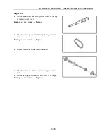
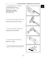
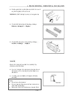


6. ENGINE REMOVAL; INSPECTION & INSTALLATION
6-52
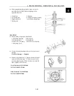
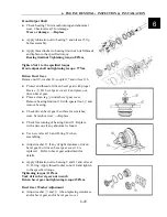
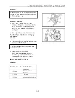
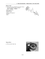
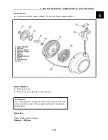
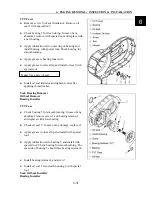
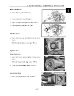
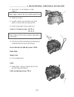
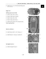
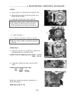
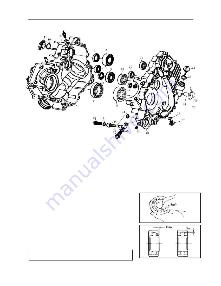
Crankcase
1. Right Crankcase 10. O-ring 19. Bearing
2. Bearing 11. Gear Sensor 20. Bearing
3. Oil Seal 12. Left Crankcase 21. Bearing
4. Bearing 13. Screw 22. Oil Dip Rod
5. Bearing 14. Oil Pipe 23. O-ring
6. Bearing 15. Link Bolt 24. Speed sensor
7. Oil Seal 16. Washer 25. Bolt
8. Washer, Reverse Gear Sensor 17. Bearing 26. Washer
9. Reverse Gear Sensor 18. Bearing 27. Oil Drainage Bolt
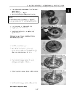
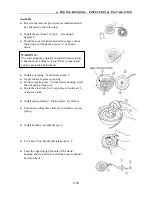
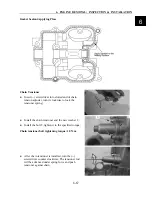
●
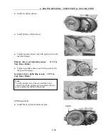
Clean and grease the bearings, turn the inner race
of bearing and check the play, noise and smooth
turning. In case of any abnormal, remove bearing
with special tool and replace;
●
Check all the oil seals for over wear or damage. In
case of any over wear or damage, remove with
special tool and replace with a new oil seal;
●
Remove gear sensor 11 and check for continuity
with reverse gear sensor 9 with a multimeter.
●
Remove link bolt and oil pipe 14 and check oil pipe
for crack or clog. Replace with a new one if any;
●
Remove oil drainage bolt 27 and clean it.
Note:
Check bearing for smooth turning after installation.
Summary of Contents for XY500UTV
Page 1: ......
Page 2: ...Service Manual XY500UTV XY500LUTV XY500UE XY500UEL 4 4 ZHEJIANG XINYANG INDUSTRY CO LTD ...
Page 16: ...1 SERVICE INFORMATION 1 13 Cables Pipes Cable Routing 1 ...
Page 17: ...1 SERVICE INFORMATION 1 14 ...
Page 18: ...1 SERVICE INFORMATION 1 15 Carburetor Condition 1 ...
Page 19: ...1 SERVICE INFORMATION 1 16 Carburetor Condition EFI Condition ...
Page 20: ...1 SERVICE INFORMATION 1 17 Carburetor Condition 1 ...
Page 21: ...1 SERVICE INFORMATION 1 18 ...
Page 41: ...2 VEHICLE BODY MUFFLER 2 20 Description of visible parts ...
Page 44: ......
Page 66: ...4 COOLING AND LUBRICATIING SYSTEM 4 2 Cooling System Illustration 4 ...
Page 114: ...6 ENGINE REMOVAL INSPECTION INSTALLATION 6 29 Primary and Secondary Sheave 6 ...
Page 225: ......


