


6. ENGINE REMOVAL; INSPECTION & INSTALLATION
6-60
●
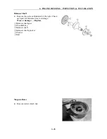
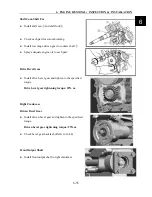
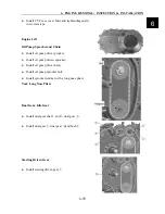
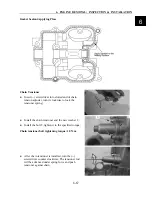
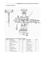
Install starting driven gear;
Magneto Rotor
●
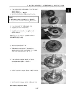
Install woodruff key into crankshaft groove;
●
Install magneto rotor 1;
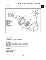
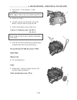
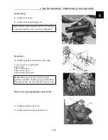
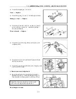
Left Crankcase Cover
●
Install dowel pin2 and gasket 3
●
Apply Lubricant grease to oil sea lip;
●
Install left crankcase cover;
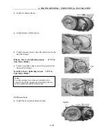
●
Install bolts;
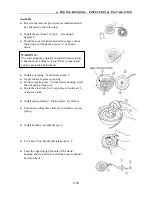
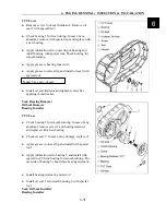
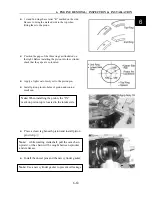
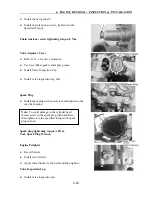
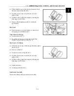
Recoil Starter
●
Install recoil starter 1
●
Install O-ring 2
●
Install washer 3 and bolt 4, tighten to the specified
torque:
Recoil starter bolt tightening torque: 55N.m.
Note:
Degrease the tapered part of rotor and crankshaft.
Use nonflammable solvent to clean off the oily or greasy
matter and fully dry the surfaces.
Note:
Use a new gasket.
Note:
Use a new O-ring and apply lubricant
grease to the O-ring
Summary of Contents for XY500UTV
Page 1: ......
Page 2: ...Service Manual XY500UTV XY500LUTV XY500UE XY500UEL 4 4 ZHEJIANG XINYANG INDUSTRY CO LTD ...
Page 16: ...1 SERVICE INFORMATION 1 13 Cables Pipes Cable Routing 1 ...
Page 17: ...1 SERVICE INFORMATION 1 14 ...
Page 18: ...1 SERVICE INFORMATION 1 15 Carburetor Condition 1 ...
Page 19: ...1 SERVICE INFORMATION 1 16 Carburetor Condition EFI Condition ...
Page 20: ...1 SERVICE INFORMATION 1 17 Carburetor Condition 1 ...
Page 21: ...1 SERVICE INFORMATION 1 18 ...
Page 41: ...2 VEHICLE BODY MUFFLER 2 20 Description of visible parts ...
Page 44: ......
Page 66: ...4 COOLING AND LUBRICATIING SYSTEM 4 2 Cooling System Illustration 4 ...
Page 114: ...6 ENGINE REMOVAL INSPECTION INSTALLATION 6 29 Primary and Secondary Sheave 6 ...
Page 225: ......


