background image

TriOxmatic

®

690

What to do if...

33

ba25314e05

09/2020

Measured value

fluctuating heavily

Incorrect temperature

display

Mechanical damage to

the sensor

– Sensor has not been calibrated 

for a long time

– Clean the outside of the 

sensor, then recalibrate 
(section 5.2 and section 4.2)

Cause

Remedy

Cause

Remedy

– Membrane head loose

– Screw the membrane cap 

tight

– Membrane does not fit snugly on 

the gold working electrode

– Change the membrane cap, 

then recalibrate (see section 
5.3 and 
section 4.2)

Cause

Remedy

– Temperature sensor defective

– Return the sensor

Cause

Remedy

– Return the sensor

Summary of Contents for 201690

Page 1: ...OPERATING MANUAL ba25314e05 09 2020 TriOxmatic 690 DISSOLVED OXYGEN SENSOR...

Page 2: ...TriOxmatic 690 2 ba25314e05 09 2020 Copyright 2020 Xylem Analytics Germany GmbH Printed in Germany...

Page 3: ...cope of delivery 8 3 2 Installation 8 3 3 Commissioning Getting the instrument ready for measuring 8 4 Measuring Operation 9 4 1 Measuring 9 4 2 Calibration 9 4 2 1 General information on calibration...

Page 4: ...4 ba25314e05 09 2020 5 8 Maintenance equipment and replacement parts 31 6 What to do if 32 7 Technical data 34 7 1 General data 34 7 2 Measurement conditions 36 7 3 Characteristic data on delivery 37...

Page 5: ...of the D O sensor 1 2 Recommended fields of application Stationary measurements in water wastewater applications 1 Protective hood 2 WP 600 membrane cap 3 Electrode unit 4 Shaft Electrode unit 5 Gold...

Page 6: ...ituation that can lead to serious irreversible injury or death if the safety instruction is not fol lowed CAUTION indicates a possibly dangerous situation that can lead to slight reversible injury if...

Page 7: ...ny other use is considered unauthorized 2 2 2 Requirements for safe operation Note the following points for safe operation The product may only be operated according to the authorized use specified ab...

Page 8: ...ning Getting the instrument ready for measuring Precision measurements Recommendation In order to carry out precision measurements leave the sensor to polarize for a longer period of time e g overnigh...

Page 9: ...calibration Why calibrate During the operation of a D O sensor the slope of the D O sensor changes with time The calibration procedure determines the current slope of the sensor When to calibrate Cali...

Page 10: ...r into the calibrating position To do so position the sensor approx 2 cm above a water surface best in a narrow bucket or similar container with water When doing so no liquid should be brought on the...

Page 11: ...e function check not in air but in air saturated water that has a higher temperature The function check is carried out in the measuring mode saturation 1 Take the sensor out of the measuring solution...

Page 12: ...value lies outside the range of precision required by the user clean the sensor shaft and membrane see section 5 2 and calibrate the sensor see section 4 2 In the case of air temperatures under 5 C d...

Page 13: ...e case of pollution according to visual check in the case of suspected incorrect measured values usually too low if the measured value lies outside the range of precision required by the user during t...

Page 14: ...ays wear protective gloves and protective goggles NOTE Clean the membrane very carefully Make sure the membrane is not damaged e g by sharp edged ob jects by laying it on sharp stones etc 4 Carefully...

Page 15: ...nce cleaning disposal and replacement 15 ba25314e05 09 2020 7 Screw the protective hood back on again 8 If necessary carefully dry the membrane with a lint free paper towel 9 Calibrate the sensor see...

Page 16: ...electrode and silver counter electrode have been cleaned NOTE Before unscrewing the membrane cap disconnect the sensor from the instrument Otherwise undesirable electrochemical reactions can oc cur t...

Page 17: ...roughly with water and consult a doctor During working activities always wear suitable protective gloves and protective goggles face shield Follow the safety datasheet 5 Unscrew the membrane cap for d...

Page 18: ...0 8 Thoroughly rinse the sensor head with electrolyte solution 9 Fill a new WP 600 membrane cap with ELY A electrolyte solution see section 5 8 MAINTENANCE EQUIPMENT AND REPLACEMENT PARTS 10 Throw awa...

Page 19: ...rotective goggles face shield Follow the safety datasheet 11 Remove any air bubbles by carefully tapping the membrane cap 12 Screw the membrane cap onto the shaft while holding the sensor at an angle...

Page 20: ...e cap and electrolyte solution NOTE Before unscrewing the membrane cap disconnect the sensor from the instrument Otherwise undesirable electrochemical reactions can oc cur that may lead to the destruc...

Page 21: ...ontact with the eyes rinse thoroughly with water and consult a doctor During working activities always wear suitable protective gloves and protective goggles face shield Follow the safety datasheet 4...

Page 22: ...tion 5 8 MAINTENANCE EQUIPMENT AND REPLACEMENT PARTS with deionized water 2 Using the rough side of the wet SF 300 polishing strip polish off any contamination from the gold working electrode using li...

Page 23: ...ver counter electrode in a beaker NOTE The reference electrode must not come into contact with the cleaning solution under any circumstances This could destroy the reference electrode and cause the se...

Page 24: ...crew cap from the safety cap of the cleaning attachment 4 Fill the screw cap with RL AG Oxi cleaning solution see section 5 8 MAINTENANCE EQUIPMENT AND REPLACEMENT PARTS 5 Screw the sensor with the sa...

Page 25: ...nd replacement 25 ba25314e05 09 2020 7 Unscrew the screw cap 8 Thoroughly rinse the electrode unit with the safety cap on with deionized water 9 Unscrew the safety cap 10 Rinse the sensor head and ele...

Page 26: ...deionized water for at least an hour 12 Carefully shake off the drops of water 13 Fill a new WP 600 membrane cap and screw it on see section 5 3 CHANGING THE ELECTROLYTE AND MEMBRANE CAP 14 Connect th...

Page 27: ...r any circumstances This could destroy the reference electrode and cause the sensor to become defective 1 Wipe the silver counter electrode with a lint free paper towel and carefully remove any loose...

Page 28: ...5314e05 09 2020 4 Leave the cleaning solution to work for 1 hour 5 Rinse the sensor head and electrode unit several times with deionized water 6 Water the sensor head and electrode unit in deionized w...

Page 29: ...accelerates the removal of oxygen from the solution The sensor should be in operation for at least 1 hour before the inspection Test procedure 8 Fill a new WP 600 membrane cap and screw it on see sect...

Page 30: ...Observe the allowed temperature range see chapter 7 TECHNICAL DATA The sensor may be stored in any position 5 7 Disposal We recommend to dispose of the sensor without the membrane cap as electronic r...

Page 31: ...n 50 ml cleaning solution polishing film ZBK 600 202 620 Replacement membrane caps 2 pieces WP 600 2 202 850 Electrolyte solution 1 bottle x 50 ml ELY A 205 212 Cleaning solution for silver counter el...

Page 32: ...sensor according to operating manual wait at least 15 minutes and recalibrate In the case of contamination that cannot be removed Exchange the membrane cap and electrolyte Cause Remedy Contaminated el...

Page 33: ...long time Clean the outside of the sensor then recalibrate section 5 2 and section 4 2 Cause Remedy Cause Remedy Membrane head loose Screw the membrane cap tight Membrane does not fit snugly on the go...

Page 34: ...surement Temperature compensation Material 199 38 40 approx 660 g Material Fluorine plastic Thickness 50 m ELY A Via integrated NTC 5 C 60 C Accuracy 0 5 K Resolution 0 1 K IMT integrated membrane tem...

Page 35: ...FCC class A Integrated lightning protection Yes Test certificates CE cUL UL Protection ring POM Cable gland V4A stainless steel 1 4571 Cable sheath PUR Length 1 5 m 7 m 15 m special lengths on request...

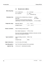
Page 36: ...0 m depth Operating position Any if the minimum approach flow is guaranteed Approach flow 5 cm s at 1 measurement accuracy D O concentration 0 0 60 0 mg l D O saturation 0 600 0 1200 mbar pO2 In the c...

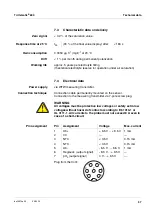
Page 37: ...n technique Connection cable permanently mounted on the sensor Connection to the measuring transmitter via 7 pole screw plug WARNING All voltages must be protective low voltages or safety extra low vo...

Page 38: ...Technical data TriOxmatic 690 38 ba25314e05 09 2020...

Page 39: ......

Page 40: ...uildings factories and farms In more than 150 countries we have strong long standing relationships with customers who know us for our powerful combination of leading product brands and applications ex...

Reviews: