Page | 22
RS485 sensors. If a full bidirectional RS232 sensor is to be used, the M12 connector is easily rewired internally to
suit. The wiring for all these options is provided in Table 2. The M12 pin numbering is as per Figure 11.
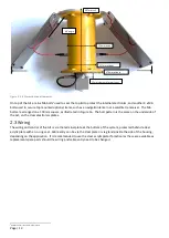
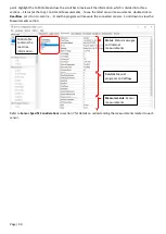
Figure 11 - M12 connector pin numbering
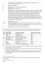
Table 2 - M12 Wiring
Wiring
M12-5
Power
Digital In
Analog In
Ground
Misc
Pin 1
Brown
Pin 2
White
Pin 3
Blue
Pin 4
Black
Pin 5
Grey
Port 1
M12 (default)
SW12V
C1
A1
GND
PSW
Port 2
2
nd
M12 (optional)
SW12V
C1
A2
GND
PSW
RS485
RS485 M12 (Default if RS485)
SW12V
C1
RS485_B
GND
RS485_A
RS232
6
RS232 M12
SW12V
C1
RS232 Rx
GND
RS232 Tx
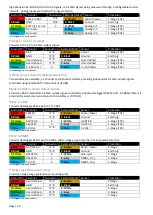
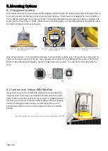
The default wiring suits a wide range of common sensors. Some of the most common sensor wiring is shown in
Table 3. Many sensors may operate with the default wiring for Port 1 or Port 2, while RS485 sensors operate with
the default wiring for stations supplied with the RS485 interface inbuilt. Cells highlighted with an asterisk
*
indicate
that this wire needs to be changed from the default wiring, inside the Ai1POLE housing. Sensor names highlighted
with a percentage symbol
%
indicate that a molded M12 cable is to be connected to the sensor. PSW is used on both
Port 1 and Port 2 so a rain gauge can be fitted to either, a common option.
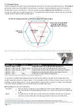
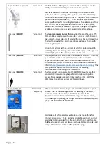
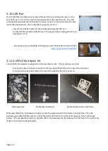
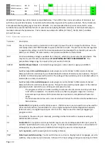
The internal terminals are labelled
along the edge with abbreviations to
fit the space. SW12V is SW,
1TB
is a
multi-function terminal that can be
either C
1
,
T
x, or RS485_
B
depending
on the solder jumpers selected, and
2RA
is a similar multi-function
terminal that can be C
2
,
R
x, or
RS485_
A
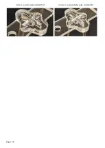
. The solder jumpers are
aligned behind to terminals as shown
here.
Table 3 - Wiring for commonly used environmental sensors, with sensor wire colors indicated by the color of the cell.
Internal M12 Pin:
Internal M12 Wire Color:
Power
Digital In
Analog In
Ground
Misc
Ai1 Port
Usage
Pin 1
Brown
Pin 2
White
Pin 3
Blue
Pin 4
Black
Pin 5
Grey
YSI EXO
(impulse pin in brackets)
SW12V
(3)
C1
(1)
RS485_B
(5)
GND
(2)
RS485_A
(6)
RS485
YSI ProDSS/SWAP
(Milspec letter in brackets)
SW12V
(A)
RS485_B
(E)
GND
(C)
RS485_A
(D)
RS485
YSI 6 Series
SW12V
C1
GND
Port 1/2
Insitu AquaTROLL
SW12V
C1
GND
Port 1/2
Observator NEP5000 Turbidity
SW12V
C1
GND
Port 1/2
ZebraTech Optical DO
(D-Opto)
SW12V
C1
GND
Port 1/2
Seabird SBE16+ Sonde
BAT*
RS232 Rx
GND
RS232 Tx
RS232
Thermistor (Modbus)
SW12V
RS485_B
GND
RS485_A
RS485
RS485 Weather Station
SW12V
RS485_B
GND
RS485_A
RS485
SDI12 Weather Station
SW12V
C1
GND
Port 1/2
Vaisala WXT536 Weather Stn.
SW12V
C1 (Blue+White)
7
GND
Port 1/2
Met2 Wind Sensor (WS/WD)
SW12V
C1
GND
Port 1/2
Pyranometer (CS320)
SW12V
C1
GND
Port 1/2
PAR Quantum Sensor (CS310)
A1
GND
Port 1/2
Sontek IQ
SW12V
C1
Orange
GND
Green
RS232
6
6
RS232 port wiring changed from serial number 31000 onwards. The old standard was white to RS232 Rx, and blue to A2. This
change was made to allow Sontek to operate with the CR300 in PortBridge() mode for remote configuration
7
Both the blue and white from the Vaisala cable are wired into C1 for SDI12 to work
1TB
2RA

