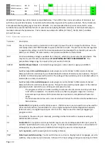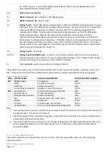
Page | 23
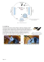
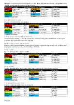
Internal M12 Pin:
Internal M12 Wire Color:
Power
Digital In
Analog In
Ground
Misc
Ai1 Port
Usage
Pin 1
Brown
Pin 2
White
Pin 3
Blue
Pin 4
Black
Pin 5
Grey
Aanderra DCS (Tx Only)
SW12V
C1_Rx
GND
Port 1/2
Aanderra DCS
SW12V
RS232 Rx
RS232 Tx
RS232
Aanderra DCPS
SW12V
RS232 Rx
GND
RS232 Tx
RS232
Generic Modbus Slave
%
SW12V
RS232 Rx
GND
RS232 Tx
RS232
Godwin X36 Controller
%
RS232 Rx
GND
RS232 Tx
RS232
WM400 Clamp-on Flow
%
SW12V
RS232 Rx
GND
RS232 Tx
RS232
AB400 Clamp-on Flow
%
SW12V
RS485_B
GND
RS485_A
RS485
Iridium Satellite transceiver
BAT*
A2
RS232 Rx
GND
RS232 Tx
RS232*
mod
Radar Level
8
SW12V
C1
GND
C2*
Port 1/2*
Ultrasonic Level (Serial, Maxb)
Vx1*
C1_Rx
GND
Port 1/2
Ultrasonic Level (Serial, Senix)
SW12V
A2(4-20mA)
9
RS232 Rx
GND
RS232 Tx
RS232*
Ultrasonic Level
4-20mA (WL705)
SW12V
A1(4-20mA)
GND
Port 1/2
4-20mA Level
(4-20mA MJK)
SW12V
A1(4-20mA)
Port 1/2
4-20mA Level (CS-PT400)
SW12V
A1(4-20mA)
Generic Analog Sensor
SW12V
A1
GND
Port 1/2
Tipping Bucket Rain Gauge
%
GND
PSW
Port 1/2
RM Young Wind Monitor
Vx1*
GND*
A1
GND
PLL*
Port 1/2*
RM Young Wind Mon
w M12cbl
WD-EXC->
Vx1*
WD-REF->
GND*
WD-SIG->
A1
EARTH->
GND
WS-SIG->
PLL*
Port 1/2*
Siren
SW12V
GND
Port 1/2
Starflow QSD (red cable)
SW12V
C1
GND
Port 1/2
Starflow QSD (brown cable)
SW12V
C1
GND
Port 1/2
Strobe light
SW12V
GND
Port 1/2
Sampler activation
SW12V
GND
Port 1/2
Data Display
Vx2*
C1
A1
GND
PSW
Port 1
Zebratech Wiper
10
(flying lead)
Red*
White*
Green*
Black*
Shield*
Port*
Zebratech Wiper
(Teledyne cable)
Black (1)
Green (4)
Red (3)
White (2)
Orange (5)
Wiper Port
3.6
Glanded Cable Entry
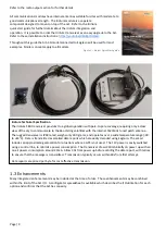
Some sensors such as pressure sensors have a pressure equalization tube that must be vented into a dry
environment to prevent condensation damage via the vent line. The M12 connector can be replaced with a PG9
Gland that uses the same size hole and can provide a weatherproof cable entry into the Ai1 housing (illustrated in
Figure 12).
3.7
Braided Wrap
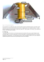
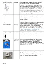
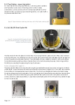
The Ai1 cable entry is shaded by the solar panel and mounting bracket,
minimizing UV damage. Braided wrap protects the cable from the underside of
the Ai1POLE to the entry into the SSPOST, to prevent UV damage, as illustrated in
Figure 12.
Figure 12
–
Braided wrap protecting sensor cable into SSPOST.
8
Must be used on C1/C2, with internal GPS connected to ComRS232 Rx which requires internal solder jumpers.
9
Only if ordered with analog output option, RS232 mode is default
10
The wiring inside the Ai1 uses a JST connector which has different colors. JST Red=M12 Brown, White = White, Green = Yellow, Black = Black and Grey = Orange.

