Page | 36
5.
Mounting Options
5.1
Navigation Lantern
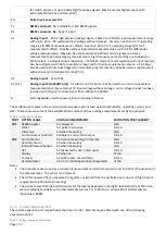
An example of the top mounted options is the navigation lantern (Figure 15), Iridium communications option (Figure
1), or top mounted instruments such as wind speed and direction. These devices are designed to mount directly to
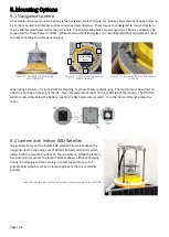
the 4 x M6 threaded holes on the top of the unit. The M6 threaded holes are arranged on a 100mm x 100mm. The
torque limit for these holes is <30Nm. While shown without bird spikes, it is recommended that bird spikes be used
to prevent nesting and solar panel fouling.
Figure 15 - Navigation light using top
mounting bolts
Figure 16 - 4 x M6 mounting bolts on
100mm square
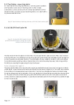
Figure 17 - Countersink bolts to hold lantern
on the lip
When using a lantern, it is turned OFF for shipping, to prevent battery discharging. The lantern must be turned on
prior to mounting on the top of the Ai1. Open the waterproof cover on the underside of the lantern. The ON/OFF
switch is accessible below the battery, next to the flash code rotary switch. Turn the lantern ON and replace the
cover.
5.2
Lantern with Iridium SBD Satellite
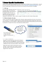
It is possible to mount the Iridium SBD satellite transceiver above the
navigation lantern by using a set of 200mm M6 extension bolts which
allows both top mounted options on the one system. While the lantern
has internal solar panels, the Iridium bracket allows sufficient charging
during the morning and the evening. Contact support for a set of
suitable bolts (which must be ordered separate to the Ai1 or satellite
bundle).
Figure 18
–
Lantern and satellite transceiver mounted on top of the Ai1BUOY
4 mounting
bolts
1
2
3
4


