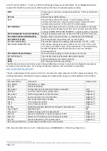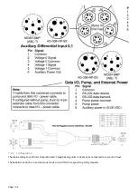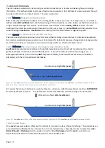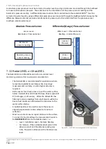
Page | 48
7.6
Sontek IQ
These instructions apply to the various versions of the Sontek IQ, including the Pipe and the Plus models. The Sontek
IQ can communicate via RS232 or via SDI12, the Ai1 uses SDI12. To allow the sensor cable to connect to the Ai1 and
to the adapter (which allows USB communications with the sensor for configuration), two connections are required,
a connector on the end of the sensor cable, and a mating connector on a short length for the adapter.
7.6.1
Adapter Cable
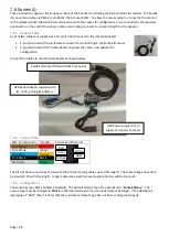
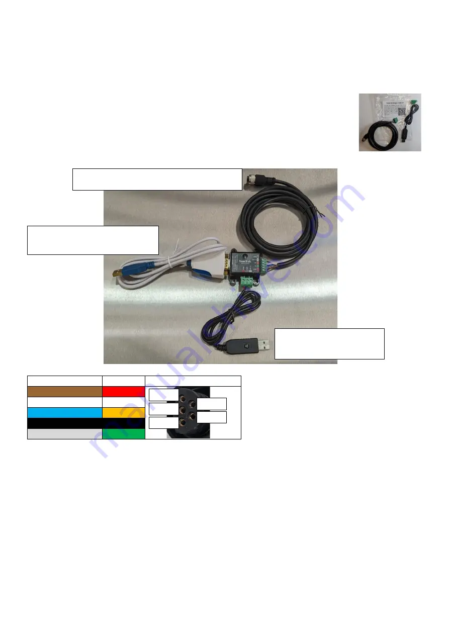
A set of two cables are supplied as a kit, which both connect to the IQ Serial Adapter:
•
5-pin terminals with 5-pin female connector for connecting to the Sontek IQ sensor
•
3-pin terminals with 12V USB adapter to power the sensor and adaptor for
configuration
Connect the cables to the IQ Serial Adapter as shown below
7.6.2
Sensor Cable
M12 Pin (Std color) IQ Cable
Sensor End Pin Colors
Pin 1 Brown
Red
Pin 2 White
White
Pin 3 Blue
Orange
Pin 4 Black
Black
Pin 5 Grey
Green
The Ai1 has been successfully tested with the Sontek IQ using cables up to 40m length. The cable voltage does drop
by around 0.2V with this length. Longer cables may work but eventually cable loss will be too much
7.6.3
Configuration
The Sontek IQ uses SDI12 address 0 (default).
The default Output Type for a Sontek IQ is “
Sontek Binary
”. The
output type must be changed to
SDI-12
in the IQ software prior to use (under Output Settings). If the FlowRate is
displaying as “NAN” then it is likely
that the instrument Output Type has not been configured properly.
Red
Green
Orange
White
Black
Sontek IQ sensor fitted with M12 connector
USB Serial Adapter supplied with
IQ, to PC running IQ software
USB Power supply (PC) to
supply 12V power to sensor


