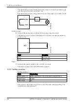
WS011301A
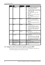
2. Install the backplane connectors on the DIN rail.
WS011302A
3. Snap the unit or units onto the DIN rail.
WS011148B
4 Mechanical Installation
14
APP 412 Installation, Operation, and Maintenance manual
Page 1: ...WR RS485 DI 1 2 3 4 GND A AI AO HMI 1 2 3 4 5 B GND 24VDC _ _ _ DI1 DI2 DI3 DI4 DO1 DO2 DO3 DO4 ALARM A ALARM B RUN COMMS RS485 USB NODE ADDRESS ON OFF MASTER SLAVE TERM DO1 NO COM NO COM T4 T3 GND DO...
Page 2: ......
Page 3: ...ls 11 3 3 Parts 11 3 4 The data plate 12 4 Mechanical Installation 13 4 1 Do not install in an explosive zone 13 4 2 Install the controller 13 4 2 1 Install the unit 13 4 3 Install the controller and...
Page 4: ...Troubleshooting 26 8 1 The unit does not work 26 9 Technical Reference 27 9 1 Dimensions 27 9 2 Environmental requirements 27 9 3 IP rating 27 9 4 Electrical data 28 9 5 RTC battery 28 9 6 Terminals 2...
Page 5: ...covered in this manual could cause death serious personal injury or damage to the equipment and the surroundings This includes any modification to the equipment or use of parts not provided by Xylem I...
Page 6: ...3 User safety Introduction All government regulations local health and safety directives must be observed Prevent danger due to electricity All danger due to electricity must be avoided Electrical con...
Page 7: ...rtified electricians or Xylem authorized mechanics Xylem disclaims all responsibility for work done by untrained unauthorized personnel 1 4 End of life product disposal Handle and dispose of all waste...
Page 8: ...admium or lead above the reference levels in 2006 66 EC or UK SI 2008 No 2164 If batteries are not properly disposed of these substances can cause harm to human health or the environment To protect na...
Page 9: ...PP 412 controller and one FPG 415 gateway for each additional mixer 2 6 5 4 3 WS011481A 7 8 9 1 Parts Number Part Product name Description 1 Mixer SR 4220 SR 4230 SR 4320 A mixer with an integrated in...
Page 10: ...election in the menus The touchscreen HMI is connected to a web server that is embedded in the controller 5 HMI FOP 315 HMI Alternative 2 A basic HMI with a jog wheel that is used for navigation and s...
Page 11: ...e pump settings through the local HMI or through a SCADA system over Modbus Data is logged by and stored in the controller All the alarms are available on the local HMI and Modbus System communication...
Page 12: ...g wheel that is used for navigation and selection in the menus 6 Computer HMI Alternative 3 The computer gives access to the same menu system as the touchscreen HMI The computer is connected to a web...
Page 13: ...3 Parts PW R RS4 85 DI 1 2 3 4 GND A AI AO HMI 1 2 3 4 5 B GND 24 VD C _ _ _ DI1 DI2 DI3 DI4 DO1 DO2 DO3 DO4 AL AR M A AL AR M B PU MP RUN C LE AN PU MP COMMS RS4 85 USB NODE AD DRES S ON OFF MAS TE R...
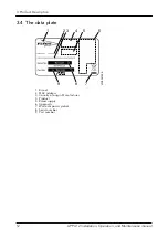
Page 14: ...9 5 7 8xxxxxx 1 Brand 2 MAC address 3 Country of origin Manufacturer 4 Product 5 Rated supply 6 Approvals 7 Waste disposal symbol 8 Serial number 9 Part number 3 Product Description 12 APP 412 Instal...
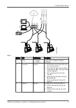
Page 15: ...ers 4 2 Install the controller 4 2 1 Install the unit Snap the unit onto the DIN rail WS009751B 4 3 Install the controller and the gateways The controller is installed with FPG 415 gateways For more i...
Page 16: ...11301A 2 Install the backplane connectors on the DIN rail WS011302A 3 Snap the unit or units onto the DIN rail WS011148B 4 Mechanical Installation 14 APP 412 Installation Operation and Maintenance man...
Page 17: ...t the path to ground is continuous WARNING Electrical Hazard Risk of electrical shock or burn A certified electrician must supervise all electrical work Comply with all local codes and regulations WAR...
Page 18: ...4 ET HE RN ET 4 7 8 3 9 0 6 1 2 5 WS011126A 3 4 5 8 6 7 1 2 FP G 4x x 1 Analog input and output 2 Digital inputs 3 HMI FOP 315 4 RS 485 Modbus RTU 5 24 VDC 6 Digital outputs 7 T3 T4 8 Ethernet Mixer o...
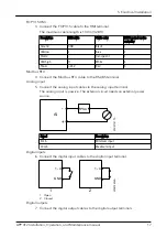
Page 19: ...Analog input 5 Connect the analog input cables to the analog input terminal The analog input is passive The external circuit needs an external power source WS011511A PSU AI Signal Description 4 mA Min...
Page 20: ...rnal power source WS011512A AO Signal Description 4 mA Minimum level 20 mA Maximum level Power 9 Connect the power cables to the 24 VDC terminal The power supply unit must fulfill isolation class II 5...
Page 21: ...RM DO 1 NO CO M NO CO M T4 T3 GN D DO 2 DO 3 NO CO M NO CO M DO 4 ET HE RN ET 4 7 8 3 9 0 6 1 2 5 PW R RS 48 5 DI 1 2 3 4 GN D A AI AO HM I 1 2 3 4 5 B GN D 24 VD C _ _ _ DI 1 DI 2 DI 3 DI 4 DO 1 DO 2...
Page 22: ...the system to OFF The groove is perpendicular to the arrow in the node address setting This image shows node address 1 RS485 DI 1 2 3 4 GND A AI AO HMI 1 2 3 4 5 B GND 24VDC _ _ _ PWR DI1 DI2 DI3 DI4...
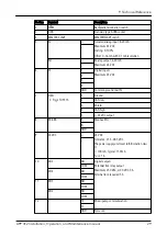
Page 23: ...Color Indication PWR Power Green The power is on 21 6 26 4 V The power is off Orange 20 0 21 6 V 26 4 29 4 V Red 20 0 V 29 4 V DI1 DI4 Digital inputs Green The digital input is active The digital inp...
Page 24: ...n The mixer pump is operating The mixer pump is not operating COMMS Mixer pump communication Green The mixer pump communication is established No mixer pump communication is established RS 485 Modbus...
Page 25: ...Indication Flashing red Flashing red The communication between the controller and the gateways in the system is lost The gateways are operating in redundancy mode 6 Operation APP 412 Installation Ope...
Page 26: ...ove the unit from the backplane 3 Remove the battery lid PW R RS4 85 DI 1 2 3 4 GND A AI AO HMI 1 2 3 4 5 B GND 24 VD C _ _ _ DI1 DI2 DI3 DI4 DO1 DO2 DO3 DO4 AL AR M A AL AR M B PU MP RUN C LE AN PU M...
Page 27: ...7 Turn on the power to the system 8 Make sure that the real time clock RTC shows the correct time 7 Maintenance APP 412 Installation Operation and Maintenance manual 25...
Page 28: ...ves voltage Restart the unit The unit does not communicate with the mixer pump Make sure that the mixer pump receives voltage Restart the mixer pump and the unit If the problem persists then contact a...
Page 29: ...er Value Operating temperature 20 C 65 C 4 F 149 F Storage temperature 20 C 70 C 4 F 158 F Operating humidity Relative humidity maximum 90 Sunlight exposure UV resistant Maximum altitude With UL appro...
Page 30: ...real time clock RTC Parameter Value Battery type BR1632 CR1632 Nominal battery voltage 3 V Battery capacity 120 mAh 9 6 Terminals PW R RS 48 5 DI 1 2 3 4 GND A AI AO HM I 1 2 3 4 5 B GND 24 VD C _ _...
Page 31: ...ommon ground earth 7 HMI Flygt FOP 315 1 Ground 2 CAN low 3 Shield 4 CAN high 5 24 VDC output 8 RS 485 A Modbus RTU B GND 9 24 VDC 24 VDC Tolerance 21 5 28 5 VDC The power supply unit must fulfill iso...
Page 32: ...Description 13 Ethernet Modbus TCP Web server 14 Backplane The Flygt controller communicates with the Flygt gateways through the backplane 9 Technical Reference 30 APP 412 Installation Operation and M...
Page 33: ......
Page 34: ......
Page 35: ......
Page 36: ...g network technologies and advanced analytics solutions for water electric and gas utilities In more than 150 countries we have strong long standing relationships with customers who know us for our po...