WS007153A
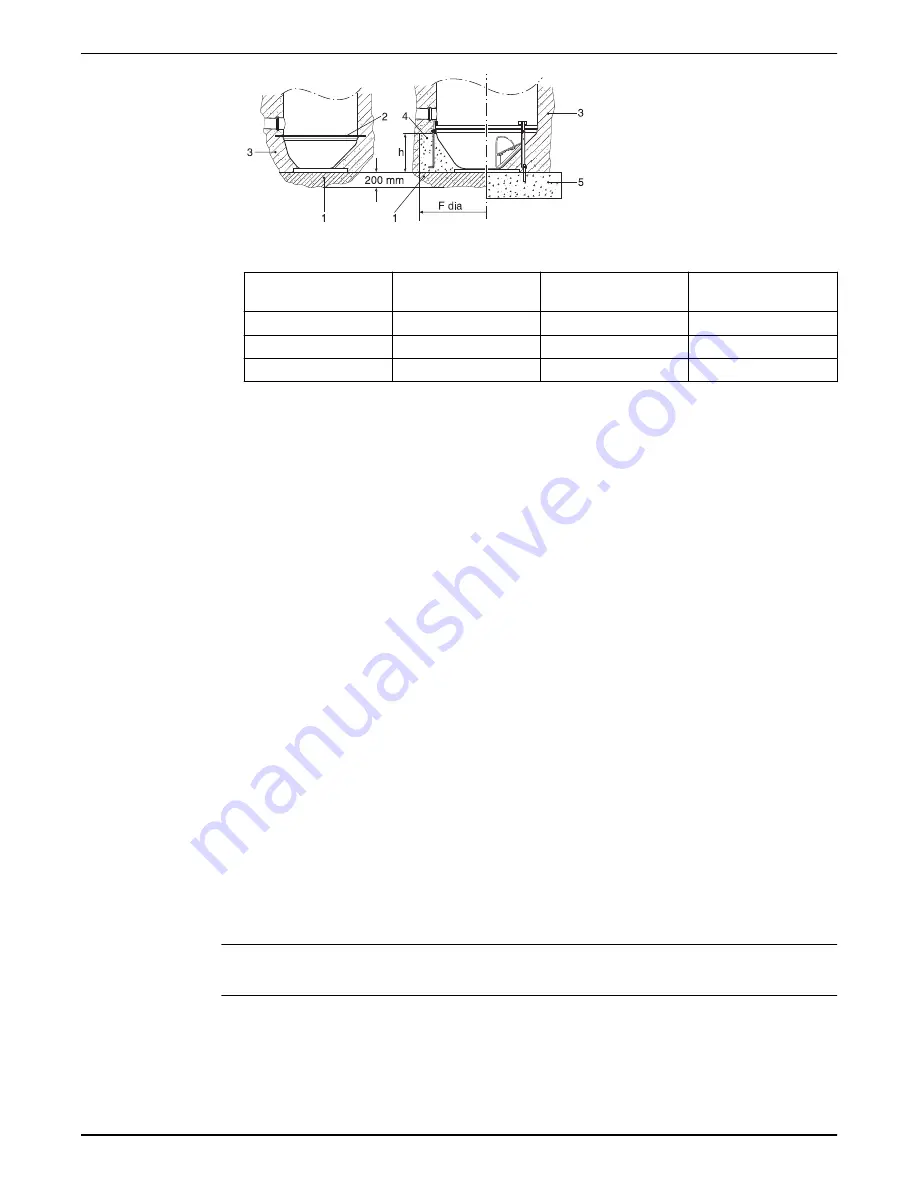
Table 4: Required dimensions for concrete footing
TOP version
Minimum diameter F,
mm
Approximated concrete
volume, m
3
Height h: Minimum -
Maximum, mm
100 S
2100
1.2 -1.6
450–550
150 S
2300
1.5–2.0
450–550
150 L
2600
2.0–2.5
450–550
Filling the unit with water up to a height of minimum 1500 mm (4.9 ft) gives sufficient
counterweight during casting.
4.2.5 Connect the external piping
Observe local regulations for frost penetration depth.
The unit is delivered complete with prefabricated inlet and discharge pipe connections as
well as connection for over-flow pipe, if ordered.
4.2.6 Make the electrical connections
Before making the electrical connections, read the Installation, Operation, and Maintenance
manual for the control panel carefully.
1. Check that the following requirements are complied with:
– The fuse in the power supply system must agree with the maximum permissible fuse
rating.
– The main voltage and frequency must agree with the specifications on the pump data
plate.
– When connecting inside the unit, remember that the environment is damp. Make sure
that suitable electrical protection is chosen accordingly.
– Do not allow the ends of the cable to be submerged in water. The water can be
sucked into the cable by capillary action.
– Appropriate support grips must be used for the cables inside the unit.
2. Install the level sensors.
See
3. Install the control panel.
See
on page 16.
4.2.7 Installing the level sensors
NOTICE:
It is essential to ensure the proper functioning of level regulators in the unit.
Install the ENM-10
Make sure that there are two ENM-10 level sensors available for start and alarm.
Before installing the level sensor, read the level sensor manual carefully.
1. Hang the level sensors on the cable holder inside the tank.
4 Installation
Flygt Top Installation, Operation, and Maintenance Manual
15


