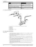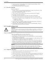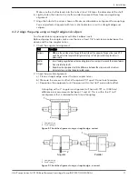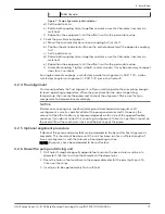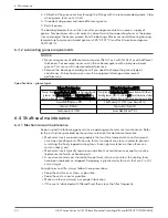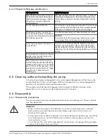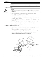
In the following Figure, the arrows show the angular misalignment:
Figure 6: Check the alignment using calipers
4.2.3 Align the pump using a dial indicator
• Make sure that each hub is secured to its respective shaft and that all connecting
and/or spacing elements are removed at this time.
• The gap between the coupling hubs is set by the manufacturer before the units are
shipped. However, this dimension should be checked. Refer to the coupling
manufacturer’s specifications supplied with the unit.
1. Check the angular misalignment:
a) Mount the dial indicator base to one coupling half, or shaft.
b) Position the dial indicator button on the front face or rear face of the opposite
coupling half.
c) Mark the index lines on the coupling halves as the following Figure shows:
P
A
R
1
1
2
3
A
Angular alignment
P
Parallel alignment
1
Dial indicators
2
Index line
4 Installation
18
G&L Pumps Series A-C 8100 Base Mounted Centrifugal Pump INSTRUCTION MANUAL

