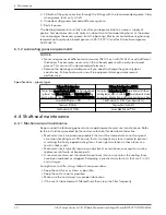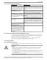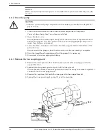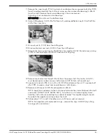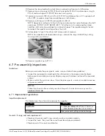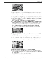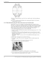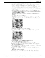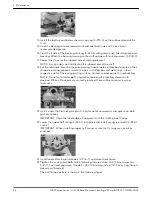
23.Rotate the shaft by hand to assure that it turns smoothly and is free from rubbing or
binding.
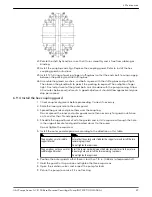
24.Install the coupling and align. Replace the coupling guard. Refer to Install the hex
coupling guard instructions.
6.9.2 Reassemble the pump with the mechanical seals on the shaft sleeve
All bearings, O-rings, seals, and gaskets should be replaced with new parts during
assembly. All reusable parts should be cleaned of all foreign matter before reassembling.
The main casing joint gasket should be made using the upper half as a template. Lay the
gasket material on the casing joint and mark it by pressing it against the edges of the
casing. Trim the gasket so that it is flush with the inside edges of the casing.
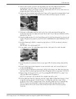
1. Assemble the impeller key (3–911–1) in the shaft key slot.
2. Apply 1/2” wide bead of Loctite or Permatex sealant to outboard end of shaft — 3” from
the impeller hub.
3. Slide sleeve (3–009–9) onto shaft, rotating the sleeve to evenly distribute the sealant
applied in step 3. On pumps built after 1991, install sleeve O-ring onto the shaft, into
the sleeve counterbore.
IMPORTANT: The pin in sleeve must seat in the impeller keyslot for proper sleeve
alignment.
4. Repeat steps 3 through 5 for the inboard shaft sleeve.
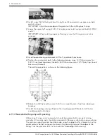
5. Assemble O-rings (3–914–2) in each casing ring (3–003–9) and slide ring onto the
impeller.
6. Press a new oil seal (3–177–9) into each stuffing box (3–073–9).
NOTE: Seal lip must point away from the bearing.
7. Lubricate and roll O-ring (3–914–1) into the groove in each stuffing box.
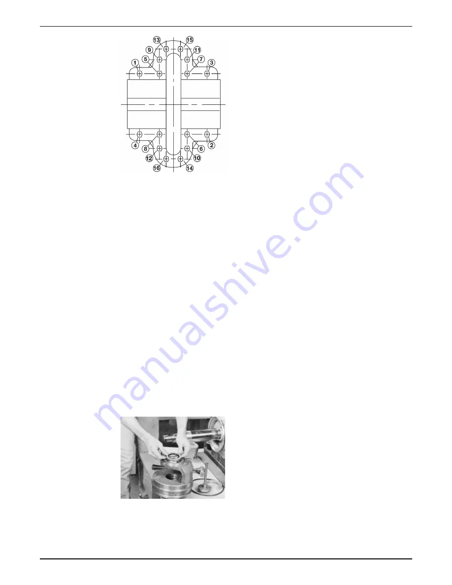
8. Press stationary seats (3–401–0) of the mechanical seals into both stuffing boxes.
Lightly lubricate the stuffing box bore to ease assembly.
6 Maintenance
44
G&L Pumps Series A-C 8100 Base Mounted Centrifugal Pump INSTRUCTION MANUAL

