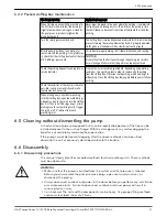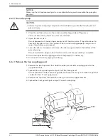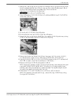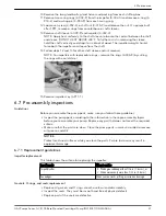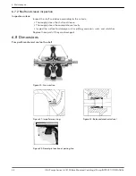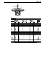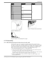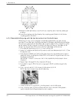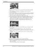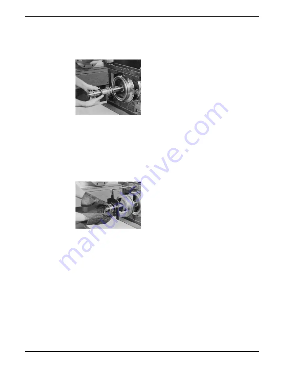
9. Obtain the set collar (3–421–9) locating dimension from the table and scribe the
dimension on the shaft sleeves. Install set collar on sleeve per dimension.
IMPORTANT: Steps 12 through 16 must be completed within 10–12 minutes to assure
proper placement of the mechanical seal.
10.Lightly coat the outboard end of the shaft sleeve with soapy water or vegetable oil and
slide the mechanical seal head (3–402–0) onto the shaft sleeve against set collar.
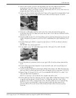
11.Slide each stuffing box onto the shaft so that the shaft end extends through the
mechanical seal area, but does not enter the oil seal. This will permit installation of the
deflector (3–136–9).
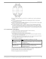
12.Slide the deflector over the shaft end; then push the shaft end through the oil seal and
slide stuffing box fully onto the shaft. DO NOT COMPRESS THE SEAL SPRING AT THIS
TIME.
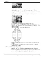
13.Heat ball bearing (3–026–4), using either dry heat or a 10–15% soluble oil and water
solution.
IMPORTANT: Do not exceed 275°F.
14.Using gloves, press the heated bearing onto the shaft against the shaft shoulder.
15.Install the locknut and lockwasher or snap ring (3–915–4) on the outboard end of the
shaft.
16.Cool the bearing to room temperature and coat both sides with two or three oz of
recommended grease.
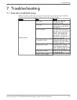
17.Coat the inside of the bearing housing (3–025–4) with grease and slide into place over
bearing. Attach the bearing housing to the stuffing box with four capscrews (3–904–9).
18.Repeat steps 12 through 16, 18, and 19, including IMPORTANT NOTE in step 11, for
inboard side of rotating element.
NOTE: A snap ring is not installed on the inboard end of the shaft.
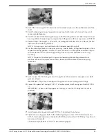
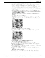
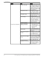
19.Set the rotating element in the pump casing. Locate both stuffing box tongues in their
respective casing grooves. Locate the pins in stuffing box and wear rings in their
respective slots at the casing parting surface. Correct and excessive O-ring buckling.
NOTE: Do not cut or damage O-rings when lowering the rotating element into
position. When all four pins are correctly located, there will be some casing ring
looseness.
6 Maintenance
G&L Pumps Series A-C 8100 Base Mounted Centrifugal Pump INSTRUCTION MANUAL
45

