INSTALLATION
The 37245-Series Quiet Flush Toilet is com plete with a
dedicated PAR-MAX 4 pump to provide either sea or
lake water to rinse the toilet bowl when flushing the toi-
let. This pump is intended to be located remotely from
the toilet but will function best if the distance from the toi-
let is kept to a min i mum. Because it is self-priming, it
may be located above the vessel’s waterline. It must be
installed with the Pumpgard strainer (pro vid ed with the
toilet) located somewhere in the inlet plumbing to the
pump. The toilet also includes a multi-function flush con-
trol which should be installed in a bulkhead location that
is convenient to the toilet and allows access for wiring to
run from the power source and to both the toilet dis-
charge pump and the PAR-MAX rinse water pump.
Install the toilet seat and lid assembly on the china bowl
with the fasteners provided and position the toilet in its
desired location. When locating the toilet, ensure there is
adequate clearance above and to the rear of the bowl so
the seat and lid assembly can rotate slightly past vertical
so it will remain up when lifted. It is all right to rotate the
waste pump assembly under the china bowl to provide
clearance from possible ob struc tions, if desired. This
can be accomplished by re mov ing the four white plastic
hex head caps from the nuts at the base of the china
bowl and removing the four machine screws and nuts
that secure the china bowl to the base. The base can
then be reattached to the bowl at any position in 90º in -
cre ments. Once the exact position for the toilet has been
de ter mined, mark the location of the four base at tach -
ment holes on the toilet mount ing sur face. De ter mine the
best toilet at tach ment meth od using 5/16
"
(8 mm) fas-
teners (either ma chine screws for through bolting or lag
screws for topside at tach ment) and drill the ap pro pri ate
size holes for the fasteners being used. If securing the
toilet with lag screws into a plywood underlayment below
fi ber glass, be sure to drill a hole through just the fi ber -
glass layer large enough to allow clear ance for the screw
threads and shank to avoid crack ing the fi ber glass.
The PAR-MAX pump should be mounted to a solid
mounting surface. It should be secured with four fas ten -
ers through the rubber grom mets that snap into the
pump’s base. Do not over-tighten the mounting screws
and crush the grommets such that they will not absorb
vibration. The pump may be mounted in any position;
how ev er, if mounting it to a vertical surface it should be
oriented so water dripping from a loose port con nec tion
will not drip down on the motor. Plumbing runs should be
kept as short and straight as possible. All plumbing
should be com plet ed with quality 3/4
"
(19 mm) hose that
will not collapse or kink. Route the inlet hose from a 3/4
"
(19 mm) through hull and seacock fitting located well
below the waterline (and well forward of any discharge
through hulls, if in stalled) to the pump inlet port. Ensure
the inlet hose passes through an accessible location
(pref er a bly above the vessel’s waterline) that will allow
for the installation of the Toilet Pumpgard strainer where
it can be pe ri od i cal ly inspected and cleaned of debris.
The Pump gard strainer should be secured with two fas-
teners to a solid mounting surface with the flow arrow
pointing towards the pump. The inlet hose should be cut
and each end attached to the strainer’s ports. The hose
from the strainer’s dis charge port must con nect with the
PAR-MAX pump’s inlet port. Provided with the toilet is a
six foot length of smooth white aes thet i cal ly pleas ing
hose to connect to the back of the toilet bowl and be
routed out of the head area. Ideally, the PAR-MAX pump
should be located so this length of hose can be con nect -
ed directly to the pump’s discharge port avoiding an
additional splice to the hose lead ing from the pump to
the back of the toilet bowl. If this is not practical, acquire
a 3/4
"
(19 mm) barb to barb hose mender and splice the
white hose to the supply hose from the discharge port of
the pump.
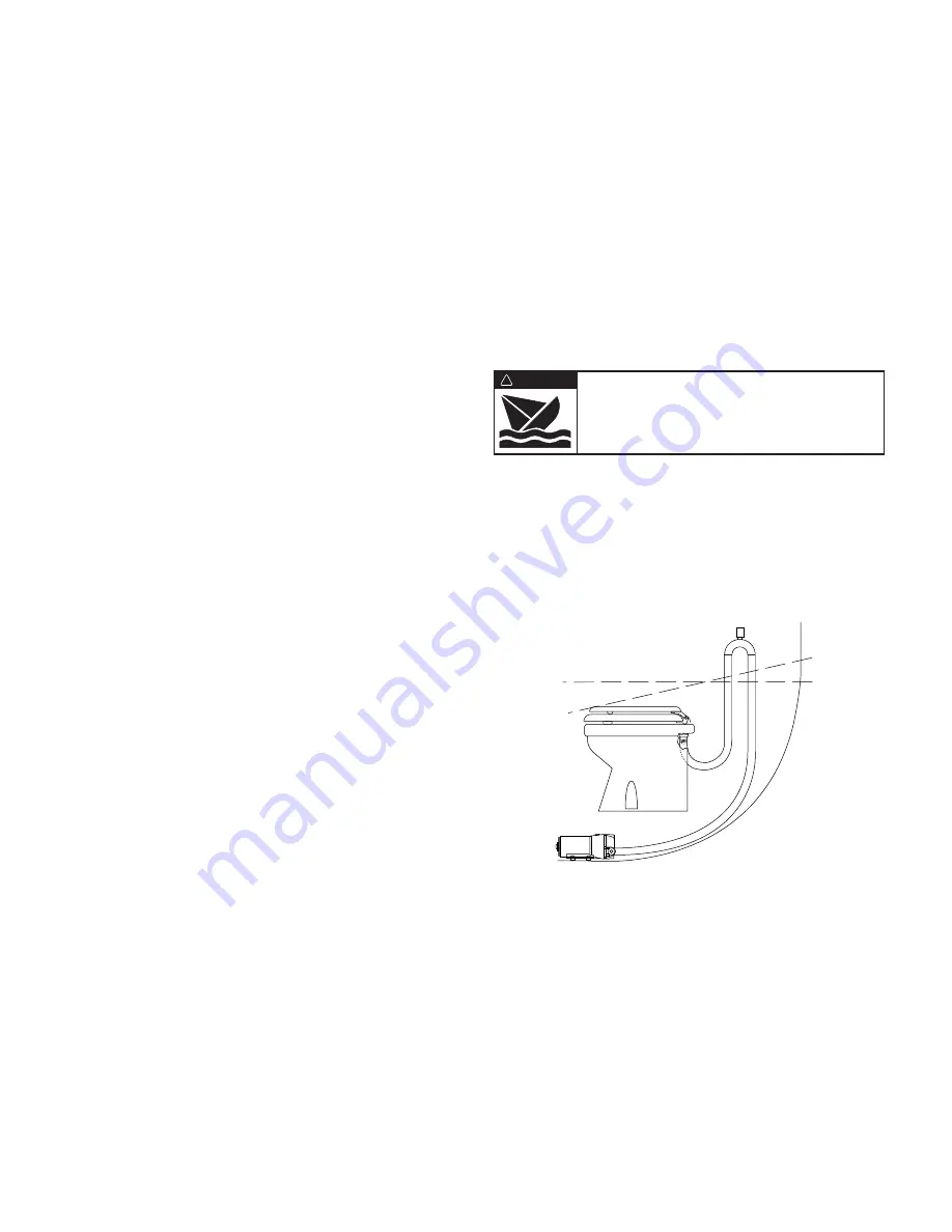
If the toilet is installed below the vessel’s wa ter line, in
order to prevent a siphon action from filling the toilet, a
properly positioned vented loop fitting must be installed
between the PAR-MAX pump and the back of the toilet
bowl. The vented loop fitting must be secured in a loca-
tion that remains at least 6-8 inches (15-20 cm) above
the waterline at all angles of heel and trim (see diagram).
The toilet discharge port is sized for 1
"
(25 mm) hose.
The discharge hose should be a quality grade re in forced
hose suitable for waste ap pli ca tions. Route the dis -
charge hose to the hold ing tank in the most direct way
with as few bends as possible. To retain some water in
the bowl, it is best to loop the discharge hose up about
8-10 inches (15-20 cm) as close to the toilet as practical
then on to the holding tank. It is best to avoid any dips or
low spots in the dis charge plumbing that can act as
water traps and collect waste. If this occurs, waste can
solidify and cause a discharge blockage.
If the toilet is plumbed to an over board discharge, and is
below the vessel’s waterline, the discharge plumbing
must include a properly positioned vented loop. The
vented loop fitting must be secured in a location that
Flood hazard. If toilet is installed below the
waterline, it must be installed with a properly
positioned vented loop in the discharge hose.
Failure to do so can result in flooding which
can cause loss of property and life.
WARNING
!
Waterline
Vented Loop
Heeled Waterline
2


