background image

22

TECHNICAL APPENDIX

The minimum operating values that can be reached 

at the pump suction end are limited by the onset of 

cavitation.

Cavitation is the formation of vapour-filled cavities 

within liquids where the pressure is locally reduced to 

a critical value, or where the local pressure is equal to, 

or just below the vapour pressure of the liquid.

The vapour-filled cavities flow with the current and

when they reach a higher pressure area the vapour

contained in the cavities condenses. The cavities 

collide, generating pressure waves that are transmitted 

to the walls. These, being subjected to stress cycles, 

gradually become deformed and yield due to fatigue. 

This phenomenon, characterized by a metallic noise

produced by the hammering on the pipe walls, is called

incipient cavitation.


The damage caused by cavitation may be magnified by

electrochemical corrosion and a local rise in 

temperature due to the plastic deformation of the 

walls. The materials that offer the highest resistance to

heat and corrosion are alloy steels, especially austenitic

steel. The conditions that trigger cavitation may be 

assessed by calculating the total net suction head, 

referred to in technical literature with the acronym 

NPSH (Net Positive Suction Head).

The NPSH represents the total energy (expressed in m.)

of the liquid measured at suction under conditions of

incipient cavitation, excluding the vapour pressure 

(expressed in m.) that the liquid has at the pump inlet.

To find the static height hz at which to install the 

machine under safe conditions, the following formula

must be verified:

hp


+


hz


 (NPSHr + 0.5) + hf + hpv

where:

hp

   is the absolute pressure applied to the free liquid

        surface in the suction tank, expressed in m. of 

        liquid; hp is the quotient between the barometric

        pressure and the specific weight of the liquid.

hz

   is the suction lift between the pump axis and the

        free liquid surface in the suction tank, expressed

        in m.; hz is negative when the liquid level is

        lower than the pump axis.

hf 

   is the flow resistance in the suction line and its

        accessories, such as: fittings, foot valve, gate

        valve, elbows, etc.

hpv

 is the vapour pressure of the liquid at the

        operating temperature, expressed in m. of

        liquid. hpv is the quotient between the Pv vapour

        pressure and the liquid’s specific weight.

0,5

  is the safety factor.

The maximum possible suction head for installation

depends on the value of the atmospheric pressure

(i.e. the elevation above sea level at which the pump

is installed) and the temperature of the liquid.

To help the user, with reference to water temperature

(4° C) and to the elevation above sea level, the 

following tables show the drop in hydraulic pressure

head in relation to the elevation above sea level, and

the suction loss in relation to temperature.

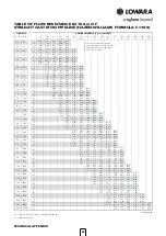
Friction loss is shown in the tables at pages 117-118 of

this catalogue. To reduce it to a minimum, especially

in cases of high suction head (over 4-5 m.) or within

the operating limits with high flow rates, we recommend 

using a suction line having a larger diameter than that 

of the pump’s suction port. It is always a good idea to 

position the pump as close as possible to the liquid 

to be pumped.

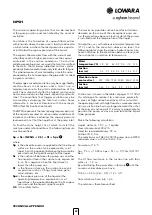
Make the following calculation:

Liquid: water at ~15°C 

γ

 = 1 kg/dm

3

Flow rate required: 30 m

3

/h

Head for required delivery: 43 m.

Suction lift: 3,5 m.

The selection is an FHE 40-200/75 pump whose NPSH

required value is, at 30 m

3

/h, di 2,5 m.

For water at 15 °C

hp =  Pa / 

γ

 = 10,33m, hpv =  Pv / 

γ 

= 0,174m (0,01701 

bar)

The Hf flow resistance in the suction line with foot 

valves is ~ 1,2 m.

By substituting the parameters in formula      with the

numeric values above, we have:

10,33 + (-3,5) ≥ (2,5 + 0,5) + 1,2 + 0,17

from which we have: 6,8 > 4,4

The relation is therefore verified.

 Water 
 temperature (°C)

   20     40     60   80    90    110    120

 Suction 
 loss (m)


                 0,2    0,7   2,0   5,0   7,4   15,4   21,5

 Elevation above


 sea level (m)


   500   1000  1500   2000    2500   3000

 Suction


 loss (m)


               0,55    1,1    1,65     2,2      2,75     3,3

NPSH

1

Summary of Contents for Lowara Scuba SC205C

Page 1: ...Cod 191005661 Rev A Ed 06 2017 50 Hz SCUBA Series CLOSE COUPLED SUBMERSIBLE ELECTRIC PUMPS ...

Page 2: ......

Page 3: ...3 CONTENTS Specifications 5 Identification code and rating plate 8 Hydraulic performance range 9 Dimensions and weights 10 Motor control panel combination table 12 Technical appendix 13 ...

Page 4: ... 15 25 35 45 55 65 75 20 30 40 50 60 70 80 Q US gpm 4 6 8 12 14 16 18 22 24 26 28 32 34 10 20 30 H ft 60 80 120 140 160 180 220 240 260 100 200 Q l min 22 1 27 7 38 7 44 3 55 3 60 9 71 9 77 5 88 5 94 1 105 1 110 7 121 7 127 3 17 33 50 66 83 100 116 133 Q Imp gpm 3 4 6 7 8 9 11 12 13 14 16 17 18 19 21 22 23 24 26 27 28 29 5 10 15 20 25 ...

Page 5: ...es 2850 rpm overload protection to be provided by user and installed in the control panel see electric panel section Maximum supply voltage variations 5 Classe F insulation Can also operate in horizontal position Maximum number of starts per hour evenly distributed 25 for motors up to 0 9 kW 20 for motors 1 1 kW Maximum temperature of water in contact with the motor 40 C continuos use CONTRUCTION ...

Page 6: ...6 SCUBA SERIES PUMP SECTION AND LIST OF MAIN COMPONENTS 04453B_C_DS 1 2 3 4 5 6 7 8 9 10 11 12 13 14 16 15 17 17 17 17 17 18 17 19 20 24 21 23 22 25 26 ...

Page 7: ... 1 X5CrNi18 10 1 4301 AISI 304 12 Upper head Tecnopolymer PPS 13 Bearing support upper Stainless steel EN 10088 1 X5CrNi18 10 1 4301 AISI 304 14 Complete falnge 15 Filter Stainless steel EN 10088 1 X5CrNi18 10 1 4301 AISI 304 16 Connection container 17 Elastomers Nitrile rubber NBR 18 External mechanical seal Silicon carbide 19 Bush bearing Tecnopolymer PU 20 Internal mechanical seal fixed part St...

Page 8: ...27 SC SCUBA series pump 2 Flow rate 2 m3 h 07 Motor power 0 75 kW Null 50 Hz Null Single phase C With capacitor G Float L27 20 m cable H07 Cable L27 20 m cable H07 Power supply M Single phase T Three phase 04466_C_SC 04467_C_SC SINGLE PHASE RATING PLATE THREE PHASE RATING PLATE LEGEND 1 Electric pump type 2 Code 3 Delivery range 4 Head range 5 Characteristics motor 6 Manufacturing data and serial ...

Page 9: ... AT 50 Hz 2 3 4 5 6 7 8 1 H m 20 30 40 50 60 70 80 10 5 6 7 8 9 20 30 10 H ft 40 50 60 70 80 90 200 100 4 5 6 7 8 9 20 10 20 30 40 50 60 70 80 90 100 SC2 SC4 ISO 9906 2012 Grade 3B Q Imp gpm 2850 rpm 04456_C_CH Q l min Q m 3 h SC2 SC4 Q US gpm ...

Page 10: ...09T 0 9 1 2 72 4 66 3 61 8 56 3 49 6 41 8 27 4 SC211C SC211T 1 1 1 5 84 5 77 6 72 6 66 3 58 6 49 2 31 7 SC407C SC407T 0 75 1 49 4 42 8 40 6 38 1 34 0 32 5 25 9 16 5 SC409C SC409T 0 9 1 2 62 5 52 3 49 6 46 7 41 8 40 1 32 2 19 9 SC411C SC411T 1 1 1 5 75 5 63 4 60 0 56 4 50 6 48 5 39 3 25 4 scuba sc2 sc4 2p50 en_c_th RATED POWER Q DELIVERY H TOTAL HEAD METRES COLUMN OF WATER DATI ELETTRICI SERIE SCUB...

Page 11: ...viscosity ν 1 mm2 sec SC2 SC4 2850 rpm ISO 9906 2012 Grade 3B 0 5 10 15 20 25 30 0 20 40 60 80 100 120 140 Q Imp gpm Q l min SC411 SC409 SC407 SC211 SC209 SC207 SC205 0 5 10 15 20 25 30 35 0 50 100 150 200 250 0 10 20 30 40 50 60 70 80 90 Q US gpm H ft H m 30 40 50 60 0 1 2 3 4 5 6 7 8 9 η Q m3 h η η η ηpSC2 η η η ηpSC4 04451A_E_CH ...

Page 12: ...C205T 0 55 0 75 1 62 11 05 SC207T 0 75 1 2 38 11 11 SC209T 0 9 1 2 2 54 15 11 SC211T 1 1 1 5 2 70 15 11 SC407T 0 75 1 2 40 11 11 SC409T 0 9 1 2 2 60 15 11 SC411T 1 1 1 5 2 85 15 11 Maximum values within operating range scuba sc2 sc4 2p50 en_b_tp For different voltage e g 220 240 V please contact our network POWER RATED PANEL TYPE ...

Page 13: ...13 TECHNICAL APPENDIX ...

Page 14: ...ch and thermal relay for overload protection Non return valve at 10 meters distance from the delivery ports plus an additional non return valve every 30 50 meters of piping Gauge and gate valve at well mouth Electronic probes or floats for protection against dry running Secure the drop cable to the pipe every 2 3 meters of piping Make sure the electric pump is installed at a safe distance from the...

Page 15: ...acket 6 Delivery pipe 7 Electrical cable for motor power 8 Electric pump bleed priming cap 9 Pressure gauge 10 Diaphragm tank 11 Gate valve 12 Control panel 13 PTC PT100 cable 14 Pressure transducer 15 Inverter Hydrovar or ResiBoost 16 Filter suggest for cable lenghts exceeding 20 meters N B For correct Inverter Motor coupling contact our sales network A0034_B_SC 16 7 9 4 2 3 1 4 15 5 8 10 12 2 2 ...

Page 16: ...16 SCUBA 50 Hz SIZING OF ETHYLENE PROPILENE EPR CABLES DOL DIRECT ON LINE STARTING ϕ ϕ ϕ ϕ ϕ ϕ ϕ ϕ TECHNICAL APPENDIX ...

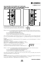
Page 17: ...er d 0 144 m operates in an 8 well well diameter D 0 203 m with flow rate Q 20 m3 h 0 0055 m3 s Speed of fluid v 0 0055 2 π 0 203 2 4 0 144 2 4 0 17 m s The minimum speed required for proper motor cooling is vm 0 20 m s Because v vm it will be necessary to mount a cooling sleeve The following formula is used to determine the maximum diameter of a cooling sleeve to be mounted on a submersible motor...

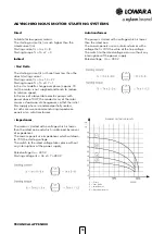
Page 18: ...is 70 the value of the line voltage The switch to the rated voltage occurs without any interruptions of the power supply Rated voltage Un 400 V Starting current Us Is In x 4 8 x In x 3 6 Un Starting torque Us Ts Tn x 2 3 x 2 Tn x 1 1 5 Un ASYNCHRONOUS MOTOR STARTING SYSTEMS Ia TECHNICAL APPENDIX Direct Suitable for low power motors The starting current Is is much higher than the rated current In S...

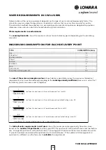
Page 19: ... bathroom and flush tank WC Coefficient for apartments with one bathroom and controlled flushing system WC Coefficient for apartments with two bathrooms and flush tank WC Coefficient for apartments with two bathrooms and controlled flushing system WC f coefficient Nr number of delivery points Na number of apartments WATER REQUIREMENTS IN CIVIL USERS Determination of the water requirement depends o...

Page 20: ...302 394 26 162 202 308 401 27 165 205 314 409 28 168 209 320 417 29 171 213 325 424 30 174 217 331 431 35 187 234 357 466 40 200 250 382 498 45 213 265 405 528 50 224 280 427 557 55 235 293 448 584 60 245 306 468 610 65 255 319 487 635 70 265 331 506 659 75 274 342 523 682 80 283 354 540 704 85 292 364 557 726 90 301 375 573 747 95 309 385 589 767 100 317 395 604 787 120 347 433 662 863 140 375 46...

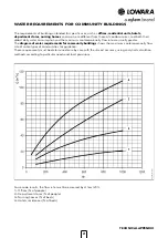
Page 21: ...località balneari maggiorare la portata almeno del 20 1 Uffici Nr di persone 2 Grandi magazzini Nr di persone 3 Case di cura Nr di posti letto 4 Hotel Residence Nr di posti letto The requirements of buildings intended for specific uses such as offices residential units hotels department stores nursing homes and so on are different from those of condominiums and both their global daily water consum...

Page 22: ...en the pump axis and the free liquid surface in the suction tank expressed in m hz is negative when the liquid level is lower than the pump axis hf is the flow resistance in the suction line and its accessories such as fittings foot valve gate valve elbows etc hpv is the vapour pressure of the liquid at the operating temperature expressed in m of liquid hpv is the quotient between the Pv vapour pr...

Page 23: ...5 0 4931 0 9710 225 498 15 25 501 0 8339 27 300 15 0 03564 0 9966 82 355 15 0 5133 0 9704 230 503 15 27 976 0 8273 28 301 15 0 03778 0 9963 83 356 15 0 5342 0 9697 235 508 15 30 632 0 8205 29 302 15 0 04004 0 9960 84 357 15 0 5557 0 9691 240 513 15 33 478 0 8136 30 303 15 0 04241 0 9957 85 358 15 0 5780 0 9684 245 518 15 36 523 0 8065 31 304 15 0 04491 0 9954 86 359 15 0 6011 0 9678 250 523 15 39 ...

Page 24: ... hr 187 63 2 17 6 6 41 2 16 0 73 0 30 v 5 10 3 02 1 99 1 27 0 82 0 57 0 42 hr 88 6 24 7 8 98 3 03 1 02 0 42 0 20 v 5 94 3 52 2 32 1 49 0 95 0 66 0 49 hr 118 32 8 11 9 4 03 1 36 0 56 0 26 v 6 79 4 02 2 65 1 70 1 09 0 75 0 55 hr 151 42 0 15 3 5 16 1 74 0 72 0 34 v 7 64 4 52 2 99 1 91 1 22 0 85 0 62 hr 188 52 3 19 0 6 41 2 16 0 89 0 42 v 5 03 3 32 2 12 1 36 0 94 0 69 0 53 hr 63 5 23 1 7 79 2 63 1 08 ...

Page 25: ...2 4 2 8 90 bend 0 4 0 6 0 9 1 1 1 3 1 5 2 1 2 6 3 0 3 9 4 7 5 8 90 smooth bend 0 4 0 4 0 4 0 6 0 9 1 1 1 3 1 7 1 9 2 8 3 4 3 9 Union tee or cross 1 1 1 3 1 7 2 1 2 6 3 2 4 3 5 3 6 4 7 5 10 7 12 8 Gate 0 2 0 2 0 2 0 4 0 4 0 6 0 9 1 1 1 3 Non return valve 1 1 1 5 1 9 2 4 3 0 3 4 4 7 5 9 7 4 9 6 11 8 13 9 G a pcv_a_th DN Equivalent pipeline length m TABLE OF FLOW RESISTANCE IN BENDS VALVES AND GATES ...

Page 26: ...8067 0 0981 1 4223 1 0000 73 5561 133 3220 0 1333 0 0013 0 0193 0 0136 1 0000 Millimetre Centimetre Metre Inch Foot Yard mm cm m in ft yd 1 0000 0 1000 0 0010 0 0394 0 0033 0 0011 10 0000 1 0000 0 0100 0 3937 0 0328 0 0109 1 000 0000 100 0000 1 0000 39 3701 3 2808 1 0936 25 4000 2 5400 0 0254 1 0000 0 0833 0 0278 304 8000 30 4800 0 3048 12 0000 1 0000 0 3333 914 4000 91 4400 0 9144 36 0000 3 0000 ...

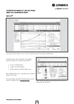
Page 27: ... products and accessories The possibility to search by applications and the detailed information output given makes it easy to make the optimal selection without having detailed knowledge about the Lowara and Vogel products The search can be made by Application Product type Duty point Xylect gives a detailed output List with search results Performance curves flow head power efficiency NPSH Motor d...

Page 28: ... possible to Set own standard units Create and save projects Share projects with other Xylect users Every registered user has a proper space where all projects are saved For more information about Xylect please contact our sales network or visit www xylect com Dimensional drawings appear on the screen and can be downloaded in dxf format FURTHER PRODUCT SELECTION AND DOCUMENTATION XylectTM ...

Page 29: ...29 ...

Page 30: ...30 ...

Page 31: ......

Page 32: ...ies that will improve the way water is used conserved and reused in the future is central to our work Our products and services move treat analyze monitor and return water to the environment in public utility industrial residential and commercial building services and agricultural settings With its October 2016 acquisition of Sensus Xylem added smart metering network technologies and advanced data...

Reviews: