


INSTRUCTION MANUAL
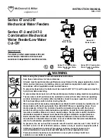
Series 47 and 247
Mechanical Water Feeders
Series 47-2 and 247-2
Combination Mechanical
Water Feeder/Low Water
Cut-Off
For steam and hot water boilers with cold
water feed, to maintain a minimum safe
water level independent of electrical service.
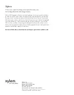
Series 47
Water Feeder
Applications:
• Before using this product read and understand instructions.
• Save these instructions for future reference.
• All work must be performed by qualified personnel trained in the proper application, instal-
lation, and maintenance of plumbing, steam, and electrical equipment and/or systems in
accordance with all applicable codes and ordinances.
• To prevent serious burns, the boiler must be cooled to 80˚F (27˚C) and the pressure must be
0 psi (0 bar) before servicing.
• To prevent electrical shock, turn off the electrical power before making electrical connections.
• The low water cut-off switch must be installed in series with all other limit and operating
controls installed on the boiler. After installation, check for proper operation of all of the
limit and operating controls, before leaving the site.
• We recommend that secondary (redundant) Low Water Cut-Off controls be installed on all
steam boilers with heat input greater than 400,000 BTU/hour or operating above 15 psi
steam pressure. At least two controls should be connected in series with the burner
control circuit to provide safety redundancy protection should the boiler experience a
low-water condition. Moreover, at each annual outage, the low water cutoffs should be
dismantled, inspected, cleaned, and checked for proper calibration and performance.
• Boiler manufacturer schematics should always be followed. In the event that the boiler
manufacturer's schematic does not exist, or is not available from the boiler manufacturer,
refer to the schematics provided in this document.
• To prevent a fire, do not use this low water cut-off to switch currents over 10.2A, 1/2 HP at
120 VAC or 5.1A, 1/2 HP at 240 VAC, unless a starter or relay is used in conjunction with it.
WARNING
CAUTION
!
WARNING
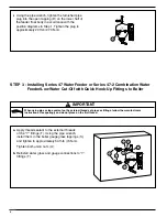
Series 47-2 Combination
Water Feeder Low Water
Cut-Off
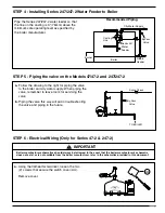
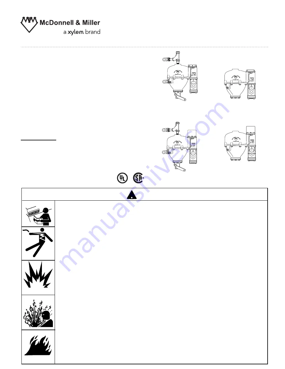
Series 247
Water Feeder
Series 247-2 Combination
Water Feeder Low Water
Cut-Off
MM-316E
California Proposition 65 warning! This product contains chemicals known to the
•
state of California to cause cancer and birth defects or other reproductive harm.
Previous controls should never be installed on a new system. Always install new
•
controls on a new boiler or system.
!


