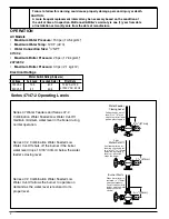
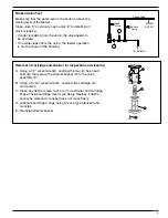
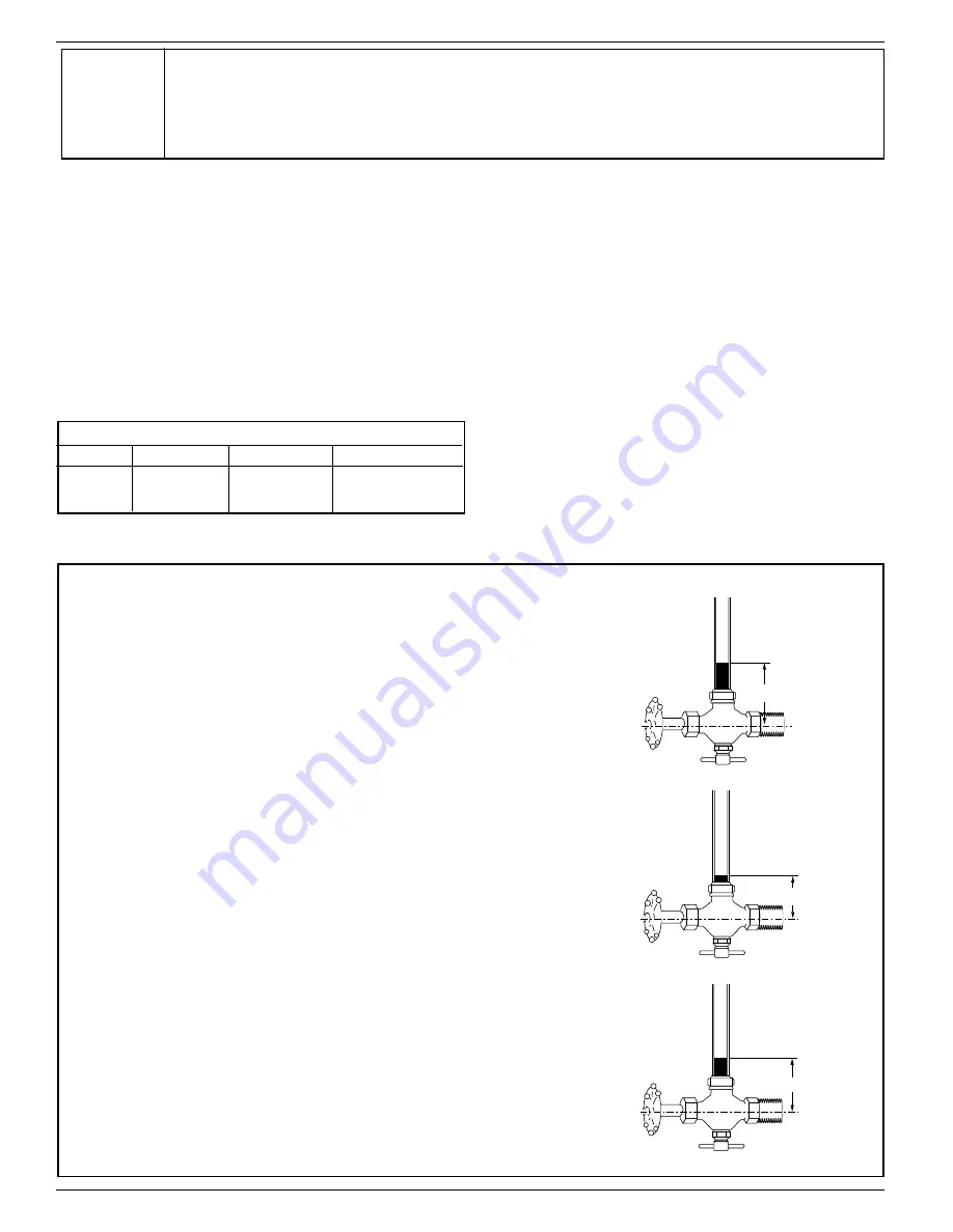
background image

Water Feeder

Closing Level

Low

Water Cut-Off

Burner Starts

2

1

/

4

" (57mm)

3

7

/

16

" (87mm)

2

3

/

4

" (70mm)

Feeder keeps water
level 3

7

/

16

" (87mm)

above center of lower
gauge glass tapping

If extreme priming or
foaming causes water
line to fall 1

3

/

16

" (30mm)

below feeder closing 
level, cut-off switch 
stops the burner

When water level is
restored 

1

/

2

" (13mm)

above emergency.
Cut-off switch starts 
burner and the water
feeder resumes
control

Motor Switch Rating (Amperes)

Voltage

Full Load

Locked Rotor

Pilot Duty

120 VAC

10.2

61.2

125 VA at 120

240 VAC

5.1

30.6

or 240 VAC, 60 Hz

OPERATION

Series 47/47-2 Operating Levels

All Models

Maximum Water Pressure:

150 psi (10.5 kg/cm

2

)

Maximum Water Temp:

120˚F (49˚C)

Water Connection Size:

1

/

2

” NPT

47/47-2

Maximum Boiler Pressure:

25 psi (1.76 kg/cm

2

)

247/247-2

Maximum Boiler Pressure:

30 psi (2.1 kg/cm

2

)

Electrical Ratings

Series 47 Water Feeders and Series 47-2
Combination Water Feeder/Low Water Cut-Off
maintain minimum water level in the boiler during
normal operation.

Series 47-2 Combination Water Feeder/Low
Water Cut-Off allows the burner to operate on
demand as the water level is restored to its
proper level.

Series 47-2 Combination Water Feeder/Low
Water Cut-Off shuts off the burner if the boiler
water level drops 1 3/16” (30mm) below the water
feeder’s closing level.

2

CAUTION:

A more frequent replacement interval may be necessary based on the condition of

the unit at time of inspection. McDonnell    Miller s warranty is one (1) year from date

of installation or two (2) years from the date of manufacture.

Failure to follow this warning could cause property damage, personal inj ury or death.

&

'

Summary of Contents for McDonnell & Miller 247 Series

Page 1: ...nt Low Water Cut Off controls be installed on all steam boilers with heat input greater than 400 000 BTU hour or operating above 15 psi steam pressure At least two controls should be connected in seri...

Page 2: ...2 NPT 47 47 2 Maximum Boiler Pressure 25 psi 1 76 kg cm2 247 247 2 Maximum Boiler Pressure 30 psi 2 1 kg cm2 Electrical Ratings Series 47 Water Feeders and Series 47 2 Combination Water Feeder Low Wat...

Page 3: ...GS PARALLEL TO BOILER WITH TURNEDY FITTINGS 3 STEP 1 Determine Best Position to Install the Water Feeder to clear obstructions that may be encountered on the side of the boiler INSTALLATION TOOLS NEED...

Page 4: ...E are greater than 14 356 mm apart invert the black Y casting F as depicted in the diagram to the bottom right and install a longer nipple G F INVERTED Y CASTING Note Reverse union nuts packing and p...

Page 5: ...onnection Slide union nut U over tailpiece P Using a pipe wrench tighten the tailpiece P into the 1 2 15 mm NPT tapping Q in the lower half of body K Tighten to 54 ft lb 74 N m 5 J H K e Remove the pl...

Page 6: ...b 74 N m Tighten both union nuts U b Reinstall water glass and gauge connections to Y fittings T When using pipe or tape sealant on the external threads of pipes or fittings follow the manufacturers i...

Page 7: ...lectrical Wiring Only for Series 47 2 247 2 AA a Using the flathead screwdriver loosen the two 2 screws that secure the switch cover AA Remove cover 7 IMPORTANT Boiler manufacturer schematics should a...

Page 8: ...in the diagram to the right Low water cut off switch and or low water alarm Pilot switch for motor starter or relay The feeder should be blown down after initial installation before leaving site It s...

Page 9: ...he flooding Broken Union Test E D B H x 4 A Using a 1 2 socket wrench unscrew the four 4 hex head bolts B that secure the strainer basket H to the valve assembly E B Using a 13 16 socket wrench unscre...

Page 10: ...er Solution Replace float e Cause Equalizing piping is plugged Solution Clean or replace piping f Cause Water supply is above 150 psi Solution Install pressure reducing valve to reduce water pressure...

Page 11: ...surfaces DO NOT use sharp objects to scrape off any accumulations of sediment or debris Unit is making noise a Cause Under certain system conditions there may be a vibration when the valve mechanism...

Page 12: ...er needs Developing new technologies that will improve the way water is used conserved and re used in the future is central to our work We move treat analyze and return water to the environment and we...

Reviews: