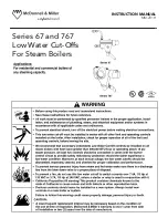
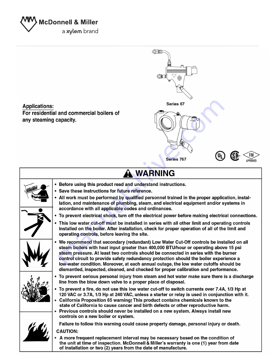
Xylem McDonnell & Miller 67 Series, Instruction Manual
The Xylem McDonnell & Miller 67 Series is a reliable and efficient product for controlling the operation of boilers and HVAC systems. Ensure proper installation and maintenance by referring to the Instruction Manual, available for free download from 88.208.23.73:8080. Keep your equipment running smoothly with this essential manual.
Share
Download

Reviews:
No comments
Related manuals for McDonnell & Miller 67 Series

Aerco BMK 750
Brand: Watts Pages: 62

Ac-U-Temp ACMSS00507
Brand: A.O. Smith Pages: 4

Henrad WH LX 30 FF
Brand: IDEAL Pages: 40

RESOLUTE RT
Brand: ENERGY KINETICS Pages: 2

CSI System
Brand: Ravenheat Pages: 52

Expansion module 1
Brand: Thermia Pages: 28

ecoTEC plus 612
Brand: Vaillant Pages: 20

EcoNox EFU 22 FF
Brand: NeOvo Pages: 48

1.5
Brand: Crestron Pages: 60

Lochinvar 3.5
Brand: Crest Audio Pages: 24

Multidea Evo 100
Brand: Bongioanni Pages: 64

BRAVA ONE OF ErP
Brand: Sime Pages: 128

CT 14
Brand: Palazzetti Pages: 140

Vitogas 200-F GS2
Brand: Viessmann Pages: 40

DuraVent DuraStack PRO DAS1
Brand: M&G Pages: 35

KSC 4 Series KSC-3090S
Brand: ECR Pages: 24

MAC-150
Brand: UTICA BOILERS Pages: 116

P-271
Brand: IBC Pages: 3


