33
Manual
US 3.10 713 FLOW CONVERTER 1905 - SW 833062
MJK Automation
Blokken 9
DK-3460 Birkerød
Denmark
Tel
+45 45 56 06 56
www.mjk.com
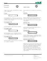
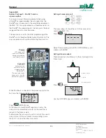
Pressure measuring circuit
Resp. (Response):
If the surface is very unsteady the level measuring itself
can be dampened with the potentiometer.
Span:
The span potentiometer is adjusted to correct level mea-
suring at high level.
Zero:
The span potentiometer is adjusted to correct measuring
at low level.
Control circuit
The control circuit is placed behind the front plate. The
display can be adjusted satisfying display here. The con-
trast will automatically be adjusted according to the sur-
rounding temperature.
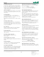
Changing the EPROM:
If the MJK 713 program should be replaced you must fol-
low these instructions:
1: Turn off the power.
2: Remove the top lid.
3: Remove the EPROM (ICI5).
4: Insert the new EPROM. The notch must face
upwards as shown on the PC board. Be careful not
to damage the EPROM.
5: Replace the top lid again and turn on the power.
Appendix D
Hardware adjustments
MJK 713 is factory adjusted to general applications. If
parts are replaced or at special applications a secondary
adjustment might be necessary. Below is shown which
adjustments might be necessary to carry out ”in field”.
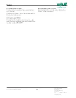
Ultrasonic measuring circuit
Gain:
With this potentiometer the signal strength of the received
signal can be adjusted. The potentiometer is normally set
in center position. At applications where there are distur-
bances close to the spread range of the sensor it might
be necessary to reduce the signal strength. E.g. small
Palmer & Bowlus flumes or when measuring is carried out
through a pipe.
In other cases where e.g. the surface is unsteady or
there are occurrences of foam, it might be necessary to
increase the signal strength. To reduce turn counterclock-
wise and to increase turn clockwise.
Resp. (Response):
If the surface is very unsteady the level measuring itself
can be dampened with the potentiometer.
Range:
The range of the potentiometer adjusts the level measur-
ing itself. To carry out an adjustment, measure the dis-
tance between the 0-point and the bottom of the sensor
and check the setting in menu no. 0.1.
Adjust then the current level and the range of the potenti-
ometer is adjusted to correct display in menu no. 0.1.
The rest of the potentiometers requires special measuring
equipment and should therefore only be adjusted by an
authorized workshop.
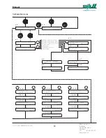
RANGE
GAIN
RESP.
MIN
MAX
FAST
SLOW
SPAN
RESP.
ZERO
FAST
SLOW
MIN
MAX
CONTRAST
ICI5


