background image


18 / 25 

 If the calibration is faulty, an error message will be displayed (see 

 chapter 8.4.2.6). 


8.4.2.6  Calibration error 

The limits for all calibration values are saved in the meter. If the entered values are outside these limits, one of 
the following error messages will be displayed: 
 

„!

Incorrect entry!

“ or „

!Calibration error!

“. 


 You may have to repeat the calibration, service the sensor or replace it (wear part!). 


Calibration method ORP 

8.5

8.5.1 

Menu structure 


8.5.2 

Calibration 

Select (

CAL

) to get to the menu item „

Calibration

“ and then on to the

 Calibration menu

 
> The calibration procedures for the respective sensor type are displayed. 
 

Choose your desired calibration procedure by selecting the respective menu item. 


The sensor must be thoroughly cleaned with distilled or deionized water prior to and between every 

measurement.


Immerse the sensor into the calibration solution and wait until a stable measured value is reached. 
 

 Ensure that the calibration medium is mixed properly and watch for the temperature balance. 


8.5.2.1  Data input 

Under menu item „

Input

“ you can enter an offset for the ORP potential. 

 
Via (

INFO

) or (

CAL

) you select the position to change. 

Via (

CONF +1

) or (

LOG -1

) you change the position. 

(

ON/OFF

) confirms and saves your setting. 

(

MEAS

) terminates the entry dialog without transferring the value. 


8.5.2.2  Temperature offset 

Under menu item „

Temp.Offs.

“ you can enter an offset for the temperature value. 

 
> Select „

Temp.Offs.

“. 


An input dialog allows you to set up the offset. This value can be positive or negative. 

 
Via (

CONF +1

) or (

LOG -1

) you change the position. 

(

ON/OFF

) confirms and saves your setting. 

(

MEAS

) terminates the entry dialog without transferring the value. 


Summary of Contents for PLF40

Page 1: ...2018 03 14 Operating Manual PTM40 PLF40 pH ORP ISE conductivity meter...

Page 2: ...User qualification 4 1 2 Specifications 4 1 3 Warning and safety information 5 1 4 2 Set up and Commissioning 6 Scope of delivery 6 2 1 Unpacking and Setup 6 2 2 Power supply 6 2 3 3 Device descriptio...

Page 3: ...eturns 25 Notes about Instructions for Use These instructions for use are intended to show you the proper and safe handling of the product For the highest possible safety you must adhere to the listed...

Page 4: ...ntion and handling of chemicals are adhered to Please observe the general see chapter 1 4 and all in the text additionally placed warnings and safety notes Specifications 1 3 Translation of the legall...

Page 5: ...rature compensation cable offset TDS factor Temperature offset One point Automatic Warning and safety information 1 4 The meter PTM40 PLF40 has the protection class III It was manufactured and tested...

Page 6: ...Use only the sensors sensor cables and interface cables recommended by the manufacturer The notes and statements in the respective user manuals and data sheets apply to the use of the sensors and fitt...

Page 7: ...f analysis parameters you must keep in mind that the sensors must be calibrated and maintained regularly The measuring input must be free of potentials and must not be connected to power conducting po...

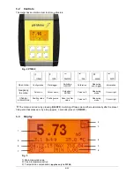
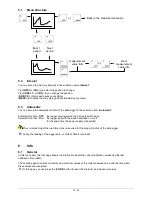
Page 8: ...t Measuring mode Cursor right Change enter values Position value 1 Position value 1 Save confirm value Cursor left Measuring mode Cursor right The meter is turned on by pressing ON OFF Switching off t...

Page 9: ...9 25 4 Temperature 5 Min main measured values 6 Max main measured values 7 Time 8 Date 9 Secondary measured value Menu structure 3 4...

Page 10: ...ly in chapter 3 4 Under General the following device relevant basic settings can be configured Display backlight and contrast Password Password Clock Clock Reset Restart device Language Language Time...

Page 11: ...e value Configuration of the switch off time 4 5 You can set the time on the meter after which the meter will be switched off automatically The data logger also records while the meter is off if the d...

Page 12: ...ogs with the device switched on or off at the same time the power supply connected The correct setting of the real time clock is required for the proper function of the data logger During the reading...

Page 13: ...clically output via the serial interface as ASCII characters Use only interface cable Interface HMG USB to transfer data from the meter to the PC This cable is not included in the delivery and must be...

Page 14: ...accessories and the pH sensor EGA142 K010 U X This combination meets the requirements to determine the pH value electro chemical process as per EN ISO 10523 2012 The meter can be used wherever you wan...

Page 15: ...he temperature of the measuring and calibration media must be measured or set up as a fixed temperature If the fixed temperature is activated it is used for temperature compensation The message FIX wi...

Page 16: ...ich the settings should be changed Asymmetry Steepness An input dialog will allow you to change the respective calibration sensor values and their respective limits If these are not reached or exceede...

Page 17: ...ompted to immerse the sensor into the third calibration medium Perform the same steps as with the first calibration solution 8 4 2 5 Automatic calibration Two and Three point The automatic calibration...

Page 18: ...horoughly cleaned with distilled or deionized water prior to and between every measurement Immerse the sensor into the calibration solution and wait until a stable measured value is reached Ensure tha...

Page 19: ...e submenu item for which the settings should be changed Asymmetry measured value 1 input value 1 An input dialog will allow you to change the respective calibration sensor values and their respective...

Page 20: ...electro chemical process as per EN 27888 1993 When connected to the sensor the meter will capture the conductivity in S or mS the temperature as well as the salinity simultaneously All Meinsberg Cond...

Page 21: ...ally selects the suitable measuring range TDS 5 shows the TDS value as a secondary variable Resist 5 shows the resistance value as a secondary variable 1 Measuring range switching possible 2 Measuring...

Page 22: ...ompensation with adjustable temperature coefficient nLF non linear temperature compensation for natural waters as per DIN EN 27888 out For measurements without temperature compensation the temperature...

Page 23: ...will be displayed Incorrect entry or Calibration error You may have to repeat the calibration service the sensor or replace it wear part 10 Scope of delivery PTM40 Set Lab pH meter Power supply Tripod...

Page 24: ...roper handling use or illegitimate opening of the device results in loss of the guarantee rights The guarantee does not cover wear parts The breach of glass parts is also excluded To ascertain the gua...

Page 25: ...GmbH Dr Karl Slevogt Stra e 1 D 82362 Weilheim Germany Service and Returns Xylem Analytics Germany Sales GmbH Co KG Sensortechnik Meinsberg Meinsberg Kurt Schwabe Stra e 6 D 04736 Waldheim Germany Te...

Reviews: