4
4
8
8.5. Installation notes
• According to ISO 4064:2013, the Cordonel meter does not require an inlet and outlet section (U0D0).
• The Cordonel meter does not require an inlet section, not even behind 90° pipe bends.
• The installation point should be the same length as the meter plus twice the thickness of the flange gaskets used.
• For outdoor installations Sensus recommends the meter display installed in a shaded location. Direct exposure to sunlight of the meter head
can increase the inner temperature of the meter, thus drastically reducing the battery life time.
• Before installation in horizontal lines, align the display in such a way that the numbers can be read easily in the intended main reading posi-
tion. (Avoid overhead positions)
• According to Directive 2014/32/EU (MID), the meters are classified in mechanical environment class M2 (considerable to strong vibrations
and shocks).
• The pipe cross-section must not be reduced or extended abruptly directly upstream or downstream of the meter. All cross-sectional changes
should be made concentrically at an angle of <8°.
• All flow regulation components (e.g. valves) must be mounted downstream of the meter in the direction of flow.
• Flange gaskets must not protrude into the pipe.
• Flush the pipe thoroughly before installing the meter.
• After installation, fill the pipe slowly to prevent damage to the meter caused by water hammers.
• Select the installation point making sure that air bubbles cannot form in the meter and the pipe is always filled completely. Do not install
the meter at the highest point of the pipe. It may be necessary to provide suitable de-airing in the direction of flow upstream of the meter.
• Use suitable measures to protect the meter against water hammers in the pipe.
• Do not carry out welding work on the pipe with the meter installed to avoid overheating.
8.6. Commissioning
After correct installation and filling, the meter automatically determines its main direction of flow. During the detection period, the two arrows
above the volume display will flash. The main direction of flow is defined as the direction of flow in which 5 m³ of water first flows after installation.
The main direction of flow is fixed when only one arrow is permanently visible in the display.
Note that the volumes that flow through the Cordonel while in testing mode are not added together to determine the main direction of flow.
8.7. Operating notes
• During normal operation, the pipe pressure upstream of the meter must not fall below 0.3 bar in order to avoid cavitation at higher flow rates.
For flow rates greater than Q
4
, the pressure downstream of the meter must be greater than 1 bar.
• The pipe should always be filled completely with water during operation.
• The manufacturer’s specification of the Q
3
must not be exceeded for a longer period of time.
• The maximum media temperature should not exceed 50 °C during operation or 70 °C at standstill.
• Avoid permanent ambient temperatures above 60 °C to enjoy full battery capacity.
9. Reading
9.1. Display description
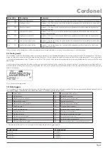
The Cordonel meter has an LC display with two lines. Numbers and symbols are displayed.
1
Volume value
2
Volume unit
3
Flow rate, pressure or temperature value
4
Flow rate, pressure or temperature unit
5
Current direction of flow
6
Radio activated (flashing)
7
Alarm flag
8
Low battery level, less than 12 months remaining
9
Meter in testing mode
10
Main direction of flow
11
,12 Not used
Cordonel
Page 5


