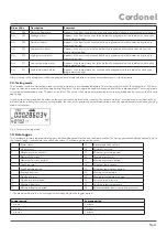
Alarm Code
Description
Comment
ALr 006
Negative flow alarm
Appears if the flow is against the main direction of flow during a pre-programmed period.
ALr 007
Leakage alarm
Appears if the flow rate has not fallen below the programmed threshold value during the
programmed period.
ALr 008
Pipe burst alarm
Appears if the flow rate has exceeded the programmed threshold value during the pro-
grammed period.
ALr 009
Low pressure alarm
Appears if the pressure has fallen below the programmed threshold value during the
programmed period.
ALr 010
High pressure alarm
Appears if the pressure has exceeded the programmed threshold value during the pro-
grammed period.
ALr 011
Low temperature alarm
Appears if the temperature has fallen below the programmed threshold value during the
programmed period.
ALr 012
High temperature alarm
Appears if the temperature has exceeded the programmed threshold value during the
programmed period.
Alarms remain in the display until either the programmed display duration is over or a reset command is issued by radio.
9.4. Testing mode
The Cordonel can be set to testing mode for testing purposes in a calibration laboratory. The testing mode switches the display to a 1000 times
higher resolution in order to achieve an optimal testing time. The testing mode can be switched on and off by radio command. The testing mode
is terminated automatically after 72 hours at the latest. The time of the automatic termination of the testing mode can be set using the Diavaso
config app.
Switching to testing mode has no effect on the previously accumulated meter reading. The volume metered in testing mode is added to the cu-
mulative meter reading. After exiting testing mode, the sum of the previously accumulated volume and the volume accumulated during testing
mode is displayed.
Fig. 5 Display in testing mode
10. Data logger
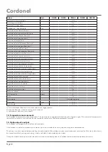
The Cordonel has two integrated data loggers, which can be parameterised and read out by radio. The first logger records data periodically, while
the second logger records data for a defined key date. The following data can be saved:
1
Alarm status
13
Absolute positive volume
2
Volume (net)
14
Minimum pressure
3
Absolute reverse volume
15
Minimum pressure period
4
Maximum flow rate *
16
Maximum pressure
5
Maximum flow rate period
17
Maximum pressure period
6
Peak flow rate **
18
Minimum temperature
7
Peak flow rate period
19
Minimum temperature period
8
Average flow rate
20
Maximum temperature
9
Pipe burst alarm
21
Maximum temperature period
10
Pipe burst alarm period
22
Last measured pressure
11
Minimum flow rate
23
Last measured temperature
12
Minimum flow rate period
24
Extended alarm status (temp. and pressure)
* ) The maximum flow rate is an averaged value depending on the logger period:
Logger period
Average period
1 minute
1 minute
2 minutes
1 minute
3 minutes
1 minute
Cordonel
Page 7


